Dodge Journey: Crossmember, front suspension
REMOVAL
1. Raise and support the vehicle.

Fig. 33: Tire And Wheel Mounting
2. On each side of the vehicle, remove the wheel mounting nuts (3), then the front tire and wheel assembly (1).
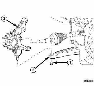
Fig. 34: Lower Ball Joint To Control Arm
3. On each side of the vehicle, remove the nut (1) attaching the lower ball joint to the lower control arm (2).
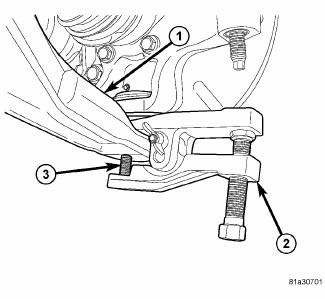
Fig. 35: Using 9360 On Lower Ball Joint
4. On each side of the vehicle, release the lower ball joint (3) from the lower control arm (1) using Remover (2), Special Tool 9360. Do not lift the knuckle out of the lower control arm at this time.
5. If equipped, remove the engine belly pan.
6. Remove the fore/aft crossmember.
7. Remove the rear engine mount.

Fig. 36: Hoses At Rear Of Crossmember
8. Remove the screws (1) securing the power steering hose routing clamps (2) to the rear of the crossmember.

Fig. 37: Heat Shield Over Gear
9. Remove the screws and push-pins securing the heat shield (1) over the right side of the steering gear (2).
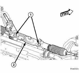
Fig. 38: Steering Gear Mounting
10. Remove the two bolts (1) securing the steering gear (2) to the crossmember.
11. Support the steering gear using a bungee cord or other to keep the steering gear from lowering when the crossmember is lowered.
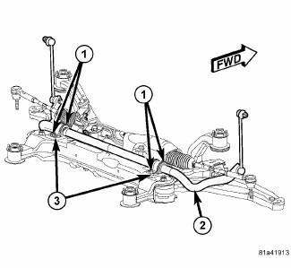
Fig. 39: Stabilizer Bar Mounting
12. Remove the screws (1) securing the stabilizer bushing retainers (3) to the crossmember.
NOTE: Before lowering the front suspension crossmember, the location of the crossmember must be marked on the body of the vehicle. Do this so the crossmember can be relocated, upon reinstallation, against the body of vehicle in the same location as before removal. If the front suspension crossmember is not reinstalled in exactly the same location as before removal, the preset front wheel alignment settings (caster and camber) may be lost.
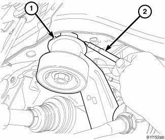
Fig. 40: Marking Location Of Crossmember
13. Using a crayon or marker (2) that will not break the paint surface, mark the location of the front crossmember (1) on the body near each mounting bolt. Do not use any type of sharp instrument that will damage the underbody of the vehicle.

Fig. 41: Front Crossmember Mounting
14. Support the crossmember (9) with a transmission jack. Secure the crossmember to the jack.
15. Remove the four mounting bolts (6) securing the front crossmember (9) to the body.
16. Remove the mounting screws (8) securing the front crossmember reinforcement brackets (7) (one each side of vehicle) to the body (1). Remove the brackets.
17. Slowly lower the crossmember and control arms to a comfortable working height using the jack.
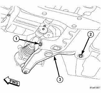
Fig. 42: Lower Control Arm Mounting
18. To remove each lower control arm:
- Remove the front bolt (1) attaching the lower control arm (3) to the front suspension crossmember.
- Remove the nut on the rear bolt (2) attaching the lower control arm (3) to the front suspension crossmember. Remove the bolt.
- Remove the lower control arm (3) from the crossmember.
INSTALLATION
1. Support the crossmember with a transmission jack. Secure the crossmember to the jack.

Fig. 43: Lower Control Arm Mounting
2. To install each lower control arm on the crossmember:
- Place the lower control arm (3) into the front suspension crossmember.
- Insert the rear bolt (2) up through the crossmember and lower control arm (3). Install the nut on the top-end of the bolt, but do not tighten it at this time.
- Install, but do not fully tighten, the front bolt (1) attaching the lower control arm (3) to the crossmember.
- With no weight or obstruction on the lower control arm, tighten the lower control arm front mounting bolt (2) to 145 N.m (107 ft. lbs.).
- With no weight or obstruction on the lower control arm, tighten the lower control arm rear mounting bolt nut to 145 N.m (107 ft. lbs.).

Fig. 44: Front Crossmember Mounting
3. Slowly raise the crossmember (9) into mounted position using the transmission jack matching the crossmember to the marked locations on the body made during removal. As the crossmember is raised, guide the lower ball joints into the mounting holes in the lower control arms. Also, make sure the stabilizer bar is properly positioned on the crossmember.
4. Position the front crossmember reinforcement brackets (7) (one each side of vehicle) over the crossmember rear mounting bushings and install the mounting screws (8), but do not tighten at this time.
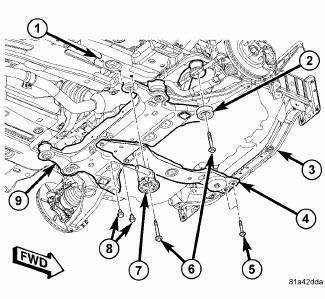
Fig. 45: Front Crossmember Mounting
5. Install the four mounting bolts (6) securing the front crossmember (1) to the body. Tighten the crossmember mounting bolts to 135 N.m (100 ft. lbs.).
6. Tighten the crossmember reinforcement bracket mounting screws (8) to 55 N.m (41 ft. lbs.).
7. Remove the transmission jack.

Fig. 46: Stabilizer Bar Mounting
8. Position both stabilizer bar bushing retainers and install the screws (1) securing the stabilizer bushing retainers (3) to the crossmember. Tighten all four stabilizer bar cushion retainer screws to 60 N.m (44 ft. lbs.).

Fig. 47: Steering Gear Mounting
9. Remove the bungee cord or other supporting the steering gear (2).
10. Install the two bolts (1) securing the steering gear (2) to the crossmember. Tighten the steering gear mounting bolts to 100 N.m (74 ft. lbs.).
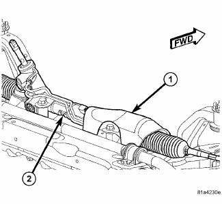
Fig. 48: Heat Shield Over Gear
11. Position the heat shield (1) over the steering gear (2). Install the mounting screws and push-pins. Tighten the screws to 6 N.m (53 in. lbs.).
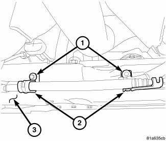
Fig. 49: Hoses At Rear Of Crossmember
12. Position the power steering hose routing clamps (2) on the crossmember. Install and tighten the screws to 8 N.m (71 in. lbs.).
13. Install the rear engine mount.
14. Install the fore/aft crossmember.
15. If equipped, install the engine belly pan.
NOTE: If a new or cleaned lower control arm is being installed, it is important to have a film of general purpose grease around the ball joint mounting hole on the lower control arm to avoid any future corrosion issues. Make sure the grease does not get inside the ball joint mounting hole or on the ball joint stud during installation.

Fig. 50: Lower Ball Joint To Control Arm
16. On each side of the vehicle, install a NEW ball joint stud nut (1). Tighten the nut to 95 N.m (70 ft. lbs.).
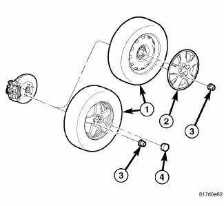
Fig. 51: Tire And Wheel Mounting
17. On each side of the vehicle, install the tire and wheel assembly (1). Install and tighten the wheel mounting nuts (3) to 135 N.m (100 ft. lbs.).
18. Lower the vehicle.
19. Perform wheel alignment as necessary.
 Crossmember, front fore and aft
REMOVAL
1. Raise and support the vehicle.
2. If equipped, remove the engine belly pan.
Fig. 29: Removing/Installing Fore/Aft Crossmember
3. Remove the front engine mount thru-bolt (2).
Fig ...
 Crossmember, rear suspension
REMOVAL
1. Raise and support the vehicle.
Fig. 52: Tire And Wheel Mounting
2. On each side of the vehicle, remove the wheel mounting nuts (3), then the
front tire and wheel assembly
(1).
Fi ...
See also:
Adjustments
ADJUSTMENT
The right and left support assemblies are slotted to allow for right/left
drive train adjustment in relation to drive
shaft assembly length.
Check and reposition right and left engin ...
EMISSIONS CONTROL SYSTEM MAINTENANCE
The Scheduled Maintenance services listed in bold type,
must be done at the times or mileages specified to ensure
the continued proper functioning of the Emissions Control
System. These, and all ot ...
Removal
WARNING: Refer to the applicable warnings and cautions for this
system before
performing the following operation. Failure to follow the warnings and
cautions may result in possible se ...
