Dodge Journey: Assembly
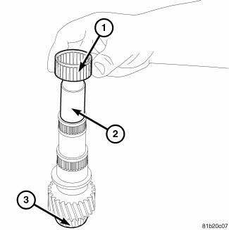
Fig. 239: Output Shaft #2 & Needle Bearing
1. Install the reverse needle bearing (1) onto the output shaft # 2 (2).
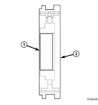
Fig. 240: Synchronizer
NOTE: Pay attention to the direction when inserting the reverse hub sleeve.
2. Install the reverse gear synchronizer onto the output shaft with (2) towards reverse gear.
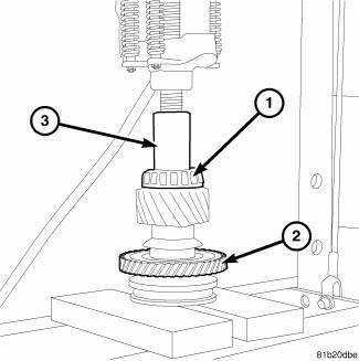
Fig. 241: Install Reverse Gear Onto Output Shaft #2
3. Install reverse gear (2) onto output shaft # 2.
4. Install reverse gear synchronizer onto output shaft using a Press (3).
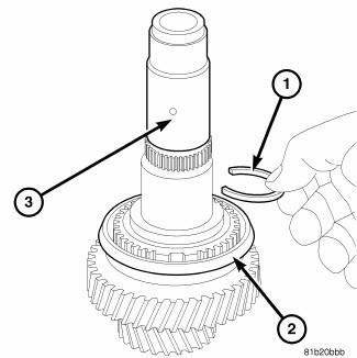
Fig. 242: Output Shaft & C-Clip
NOTE: Always use the largest snap that will fit into the grove.
5. Install the new snap ring (2) from the output shaft # 2.
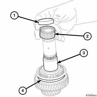
Fig. 243: #2 Bearing & Spacer
6. Install fifth needle bearing (2) and spacer (1) onto output shaft # 2 (3).
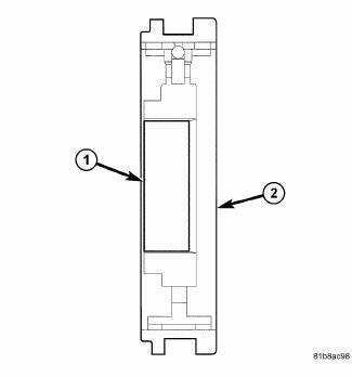
Fig. 244: Synchronizer
NOTE: Pay attention to the direction when inserting the 5th-6th hub sleeve.
7. Install the fifth gear and fifth/sixth gear synchronizer onto the output shaft with (2) towards fifth gear.
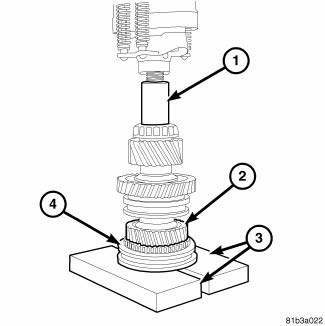
Fig. 245: 5th Gear & Synchronizer
8. Use a press to install fifth gear and fifth/sixth gear synchronizer (2).
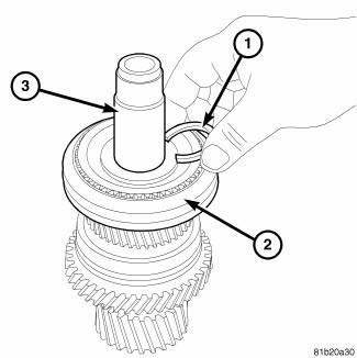
Fig. 246: Snap Ring At Output Shaft #2
NOTE: Always use the largest snap that will fit into the grove.
9. Install the new snap ring (1) from the output shaft.
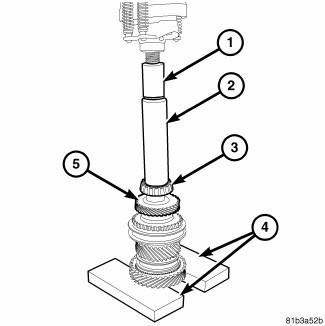
Fig. 247: Sixth Gear & Bearing
10. Install spacer sixth needle bearing and sixth gear onto shaft 11. Use Sleeve C-3717 to press sixth gear and bearing (3) onto shaft.
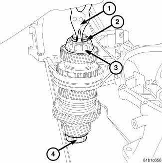
Fig. 248: Snap Ring At Output Shaft
NOTE: Always use the largest snap that will fit into the grove.
12. Install the new snap ring (2) from the output shaft.
 Disassembly
Fig. 229: Snap Ring At Output Shaft
1. Using Snap Ring Pliers (1) remove the snap ring (2) from the output shaft
# 2.
Fig. 230: Bearing From Cluster Shaft
2. Using a press, blocks, Bearing Sp ...
 Switch, backup lamp
REMOVAL
Fig. 249: Back-Up Lamp Switch
1. Disconnect battery negative cable.
2. Raise vehicle on hoist.
3. Disconnect backup lamp switch connector.
4. Remove backup lamp switch (1).
INSTA ...
See also:
Frame
SPECIFICATIONS
FRAME DIMENSIONS
Frame dimensions are listed in metric scale. All dimensions are from center
to center of Principal Locating
Point (PLP), or from center to center of PLP and fasten ...
Module, power, front blower motor
DESCRIPTION
Fig. 27: Blower Mtr Pwr Module
A blower motor power module is used on this model when equipped with the
automatic temperature control (ATC) heating-A/C system. Models equipped with t ...
Standard procedure
REFRIGERANT SYSTEM SERVICE EQUIPMENT
WARNING: Refer to the applicable warnings and cautions for this
system before
performing the following operation. Failure to follow these instructio ...
