Dodge Journey: Frame
SPECIFICATIONS
FRAME DIMENSIONS
Frame dimensions are listed in metric scale. All dimensions are from center to center of Principal Locating Point (PLP), or from center to center of PLP and fastener location.
VEHICLE PREPARATION
Position the vehicle on a level work surface. Using screw or bottle jacks, adjust the vehicle PLP heights to the specified dimension above a level work surface. Vertical dimensions can be taken from the work surface to the locations indicated were applicable.
VEHICLE PREPARATION INDEX

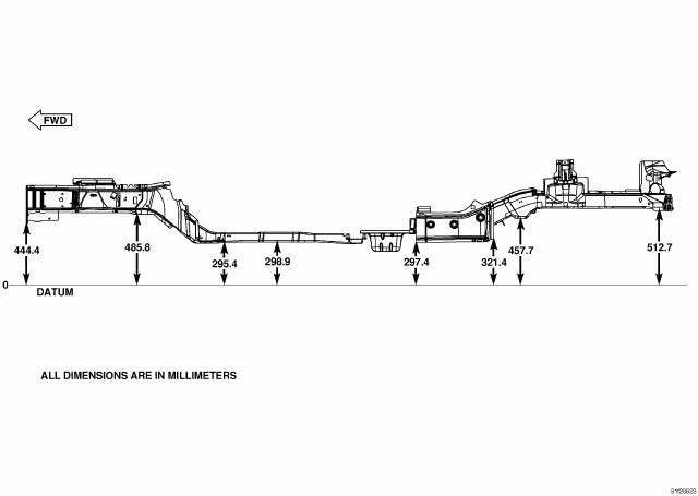
Fig. 27: Frame Dimensions - Side View
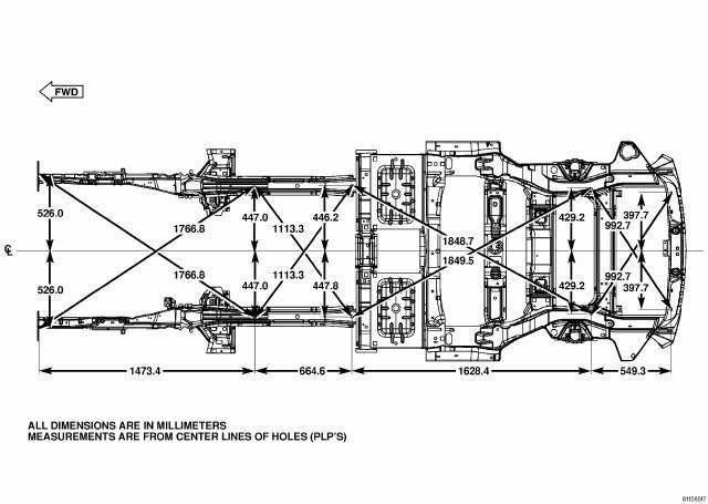
Fig. 28: Frame Dimensions - Bottom View
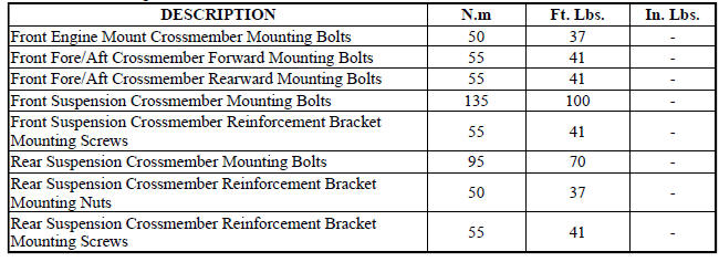
FASTENER TORQUE
 Reinforcement, bumper, rear
REMOVAL
Fig. 25: Rear Bumper Reinforcement
1. Remove rear fascia. See Removal .
2. Support bumper reinforcement (1) on a suitable lifting device.
3. Mark position of bolts (2) on frame rail ...
 Crossmember, front fore and aft
REMOVAL
1. Raise and support the vehicle.
2. If equipped, remove the engine belly pan.
Fig. 29: Removing/Installing Fore/Aft Crossmember
3. Remove the front engine mount thru-bolt (2).
Fig ...
See also:
Without intermediate shaft
NOTE: The inner tripod joints are designed with a retention feature
that prevents the
tripod rollers from coming out of the inner joint housing up to a specific
load. If
this feature is o ...
Diagnosis and Testing
LOWER BALL JOINT
1. Raise the vehicle allowing the front suspension to hang.
2. Remove the tire and wheel assembly.
3. Using Dial Indicator C-3339A, or equivalent, attach the dial indicator mou ...
Sensor, speed, input
DESCRIPTION
Fig. 369: Removing/Installing Input Speed Sensor
- INPUT SPEED SENSOR
The Input Speed Sensor (1) , is a two-wire magnetic pickup device that
generates AC signals as rotation oc ...
