Dodge Journey: Reinforcement, bumper, rear
REMOVAL
Fig. 25: Rear Bumper Reinforcement
1. Remove rear fascia. See Removal .
2. Support bumper reinforcement (1) on a suitable lifting device.
3. Mark position of bolts (2) on frame rail to aid in installation.
4. Remove bolts (2) attaching rear bumper reinforcement (1) to frame rail.
5. Remove bumper reinforcement (1) from vehicle.
INSTALLATION

Fig. 26: Rear Bumper Reinforcement
1. Position rear bumper reinforcement (1) on vehicle.
2. Install bolts (2) attaching bumper reinforcement to frame rail. Use marks made previously to properly position bumper reinforcement.
3. Tighten bolts (2) to 28 N.m (250 in. lbs.).
4. Install rear fascia.
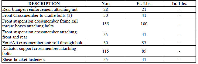
SPECIFICATIONS
FASTENER TORQUE
 Reinforcement, bumper, front
REMOVAL
Fig. 23: Front Bumper Reinforcement
1. Remove the front fascia. See Removal .
2. Support bumper reinforcement (3) on a suitable lifting device.
3. Mark the position of the bolts (1) ...
 Frame
Frame
SPECIFICATIONS
FRAME DIMENSIONS
Frame dimensions are listed in metric scale. All dimensions are from center
to center of Principal Locating
Point (PLP), or from center to center of PLP and fasten ...
See also:
Installation
CAUTION: Be certain to adjust the refrigerant oil level when
servicing the A/C
refrigerant system. Failure to properly adjust the refrigerant
oil level will prevent the A/C system fro ...
Speaker
OPERATION
Two wires connected to each speaker, one feed circuit (+) and one return
circuit (-), allow the audio output signal electrical current to flow through
the voice coil. The wiring informa ...
VEHICLE STORAGE
If you will not be using your vehicle for more than
21 days you may want to take steps to preserve your
battery. You may:
• Remove the IOD (Ignition Off-Draw) mini-fuses from
the Totally Integra ...
