Dodge Journey: Reinforcement, bumper, rear
REMOVAL
Fig. 25: Rear Bumper Reinforcement
1. Remove rear fascia. See Removal .
2. Support bumper reinforcement (1) on a suitable lifting device.
3. Mark position of bolts (2) on frame rail to aid in installation.
4. Remove bolts (2) attaching rear bumper reinforcement (1) to frame rail.
5. Remove bumper reinforcement (1) from vehicle.
INSTALLATION

Fig. 26: Rear Bumper Reinforcement
1. Position rear bumper reinforcement (1) on vehicle.
2. Install bolts (2) attaching bumper reinforcement to frame rail. Use marks made previously to properly position bumper reinforcement.
3. Tighten bolts (2) to 28 N.m (250 in. lbs.).
4. Install rear fascia.
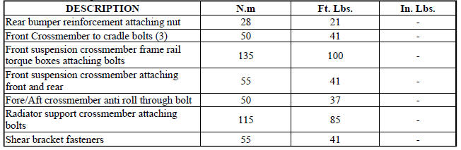
SPECIFICATIONS
FASTENER TORQUE
 Reinforcement, bumper, front
REMOVAL
Fig. 23: Front Bumper Reinforcement
1. Remove the front fascia. See Removal .
2. Support bumper reinforcement (3) on a suitable lifting device.
3. Mark the position of the bolts (1) ...
 Frame
Frame
SPECIFICATIONS
FRAME DIMENSIONS
Frame dimensions are listed in metric scale. All dimensions are from center
to center of Principal Locating
Point (PLP), or from center to center of PLP and fasten ...
See also:
Module, heated seat
DESCRIPTION
Fig. 4: Locating Heated Seat Module
The heated seat module (2) is located under the driver front seat. It has a
single electrical connector (1) and a
push pin style retainer that se ...
Tube, exhaust gas recirculation (EGR)
Removal
2.7L - LOWER TUBE
Fig. 50: Lower Exhaust Gas Recirculation Tube - 2.7L
WARNING: The normal operating temperature of the exhaust gas
recirculate (EGR)
valve and tube is very ...
Description, Operation
DESCRIPTION
Fig. 1: Identifying 41TE Automatic Transaxle Components
- TRANSAXLE CASE
- TORQUE CONVERTER
- OIL PUMP
- INPUT SPEED SENSOR
- UNDERDRIVE CLUTCH
- OVERDRIVE CLUTCH
- REVE ...
