Dodge Journey: Synchronizer
DISASSEMBLY
Place synchronizer in a clean shop towel and wrap. Press on inner hub. Carefully open up shop towel and remove springs, balls, keys, hub, and sleeve.
CLEANING
Do not attempt to clean the blocking rings in solvent. The friction material will become contaminated. Place synchronizer components in a suitable holder and clean and air dry.
INSPECTION
Proper inspection of components involve:
- Teeth, for wear, scuffed, nicked, burred, or broken teeth
- Keys, for wear or distortion
- Balls and springs, for distortion, cracks, or wear
If any of these conditions exist in these components, replace as necessary.
ASSEMBLY
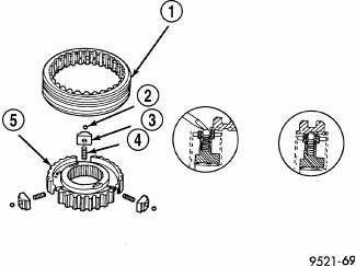
Fig. 251: Synchronizer Assembly
- - SLEEVE
- - BALL
- - KEY
- - SPRING
- - HUB
1. Position synchronizer hub (5) onto a suitable holding fixture (input shaft). The synchronizer hubs (5) are directional. The hubs must be installed with the U facing upward.
2. Install springs (4) into hub slot.
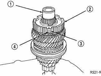
Fig. 252: Inserting Synchronizer Balls Into Keys
- - INPUT SHAFT
- - HUB
- - KEY
- - BALL
3. Insert key (3) into hub (2) and spring.
4. Apply petroleum jelly to the hole in the key. Insert balls (4) into each key.
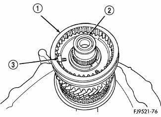
Fig. 253: Identifying Synchronizer Sleeve, Input Shaft, & Key
- - SLEEVE
- - INPUT SHAFT
- - KEY
5. Slide sleeve (1) over the hub and depress balls as you carefully slip the sleeve into position .
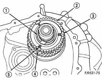
Fig. 254: Centering Synchronizer Keys & Balls By Pushing On Both Stop Rings
- - SNAP RING
- - CLUTCH
- - KEY
- - BALL
- - SPRING
6. Line up stop ring tang over the keys in the hub, install stop rings, center the keys (3) and balls (4) by pushing on both stop rings.
 Switch, backup lamp
REMOVAL
Fig. 249: Back-Up Lamp Switch
1. Disconnect battery negative cable.
2. Raise vehicle on hoist.
3. Disconnect backup lamp switch connector.
4. Remove backup lamp switch (1).
INSTA ...
See also:
VEHICLE LOADING
The load carrying capacity of your vehicle is shown on
the “Vehicle Certification Label.” This information
should be used for passenger and luggage loading as
indicated.
Do not exceed the spec ...
Seal, input flange
REMOVAL
Fig. 80: Removing /Installing Propeller Shaft
NOTE: Rubber coupler is part of the propeller shaft assembly. Removing
coupler from
propeller shaft will result in vibration/balance i ...
MIRRORS
Inside Day/Night Mirror
A two-point pivot system allows for horizontal and
vertical mirror adjustment. Adjust the mirror to center on
the view through the rear window.
Headlight glare can be reduc ...
