Dodge Journey: Installation
CAUTION: To prevent damage to the plastic evaporator tube bracket, carefully guide the heater core tubes past the bracket during installation of the heater core.
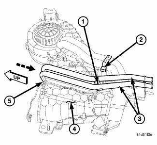
Fig. 278: Rear Heater Core Install
1. Carefully install the rear heater core (5) into the rear heater-A/C housing (4). Guide the heater core tubes past the plastic evaporator tube bracket (2). Make sure that the foam seals are properly installed.
2. Install the screw (1) that secures the rear heater core tubes (3) to the outboard side of the rear heater-A/C housing. Tighten the screw to 1.2 N.m (10 in. lbs.).
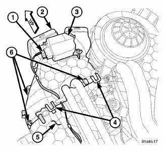
Fig. 279: Rear Distribution Housing Removal/Installation
3. Position the rear heater-A/C distribution housing (2) to the rear heater-A/C housing (5) and engage the five plastic retaining tabs (4). Make sure the retaining tabs are fully engaged.
4. Install the three metal retaining clips (6) that secure the rear distribution housing to the rear heater-A/C housing.
5. Connect the wire harness connector (1) to the rear mode door actuator (3).
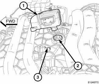
Fig. 280: Rear Blend Door Actuator Align
6. Position the rear blend door actuator (1) onto the rear heater-A/C housing (3). If necessary, rotate the actuator slightly to align the splines on the actuator output shaft with those on the rear blend-air door pivot shaft (2).
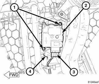
Fig. 281: Rear Blend Door Actuator Removal/Installation
7. Install the two screws (1) that secure the rear blend door actuator (2) to the rear heater-A/C housing (4).
Tighten the screws to 1.2 N.m (10 in. lbs.).
8. Connect the wire harness connector (3) to the rear blend door actuator.
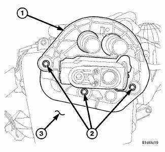
Fig. 282: Rear Housing Flange
9. Position the flange (1) to the bottom of the rear heater-A/C housing (3) and install the three retaining screws (2). Tighten the screws to 1.2 N.m (10 in. lbs.).
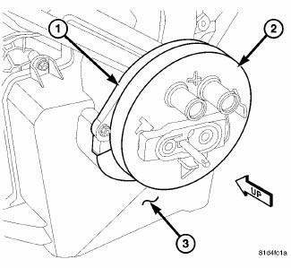
Fig. 283: Rear Housing Flange Seal
10. Install the foam seal (2) onto the flange (1) at the bottom of the rear heater-A/C housing (3). Make sure that the foam seal is properly installed.
11. Install the rear heater-A/C housing.
12. Reconnect the negative battery cable.
13. If the rear heater core is being replaced, flush the cooling system.
14. Refill the engine cooling system.
15. Evacuate and charge the refrigerant system.
 Removal
WARNING: Refer to the applicable warnings and cautions for this
system before
performing the following operation. Failure to follow these instructions
may result in serious or fatal ...
 Evaporator, A/C
...
See also:
Description, Operation
DESCRIPTION
Fig. 430: Identifying Valve Body Assembly
- VALVE BODY
- T/C REGULATOR VALVE
- L/R SWITCH VALVE
- CONVERTER CLUTCH CONTROL VALVE
- MANUAL VALVE
- CONVERTER CLUTCH SWITCH V ...
Installation
2.4L
Fig. 17: Removing/Installing Ignition Coil
1. Install ignition coil onto spark plug.
Fig. 18: Removing/Installing Ignition Coil Mounting Bolts
2. Install ignition coil mounting bolt, tigh ...
Description, Operation
DESCRIPTION
Fig. 238: Evaporator Description
NOTE: LHD model shown. RHD model similar.
The A/C evaporator (1) for the heating-A/C system is mounted in the HVAC
housing, which is located be ...
