Dodge Journey: Installation
2.4L
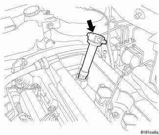
Fig. 17: Removing/Installing Ignition Coil
1. Install ignition coil onto spark plug.
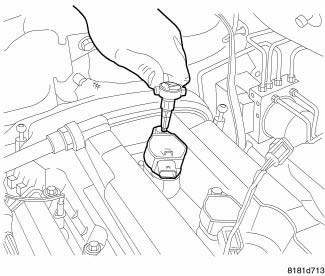
Fig. 18: Removing/Installing Ignition Coil Mounting Bolts
2. Install ignition coil mounting bolt, tighten to 9 N.m (79.5 in. lbs.).
3. Connect ignition coil electrical connectors.
4. Connect negative battery cable, tighten nut to 5 N.m (45 in. lbs.).
5. Install engine cover.
2.7L
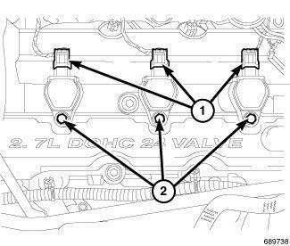
Fig. 19: Removing/Installing Electrical Connectors And Mounting Bolts At
Ignition Coil
1. Align ignition coil with top of spark plug.
2. Twist and push down ignition coil assembly onto spark plug and valve cover. Install mounting bolt (2) and tighten to 7.5 N.m (65 in. lbs.).
3. Connect electrical connector (1) to ignition coil.
4. Install upper intake manifold.
5. Connect negative battery cable.
3.5L
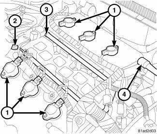
Fig. 20: Ignition Coils And Fuel Rail
1. Install ignition coil (1).
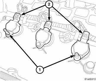
Fig. 21: Ignition Coils
2. Install engine cover studs (1) in the two outside ignition coils on the front of the engine. Install bolts on the other ignition coils.
3. Tighten studs and bolts to 8 N.m (71 in. lbs.).
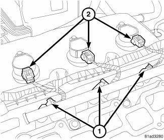
Fig. 22: Identifying Coil & Fuel Injector Connectors
4. Connect electrical connector and lock (2).
5. Install intake manifold.
6. Connect negative battery cable and tighten nut to 5 N.m (45 in. lbs.).
7. Install engine cover.
 Removal
2.4L
Fig. 11: Identifying Ignition Coil Electrical Connectors
NOTE: Prior to removing coil, spray compressed air around coil top to
make sure no
dirt drops into the spark plug tube.
The ...
 Module, glow plug
DESCRIPTION
Fig. 23: Locating Diesel Glow Plug Control Module
The glow plug control module is mounted to the fuel filter/water separator
bracket, and is controlled by the
engine control module. ...
See also:
MEDIA CENTER 230 (REQ) — AM/FM STEREO RADIO AND 6–DISC CD/DVD CHANGER
(MP3/WMA AUX JACK)
NOTE: The radio sales code is located on the lower right
side of the radio faceplate.
REQ Radio
Operating Instructions - Radio Mode
NOTE: The ignition switch must be in the ON or ACC
position t ...
Seal(s), valve guide
REMOVAL
Fig. 139: Valve Stem Seal-Removal/Installation
- VALVE SEAL TOOL
- VALVE STEM
1. Remove valve spring.
2. Remove valve stem seal by using a valve seal tool.
INSTALLATION
Fig. ...
Crossmember, rear suspension
REMOVAL
1. Raise and support the vehicle.
Fig. 52: Tire And Wheel Mounting
2. On each side of the vehicle, remove the wheel mounting nuts (3), then the
front tire and wheel assembly
(1).
Fi ...
