Dodge Journey: Standard procedure
CYLINDER HEAD OIL GALLERY CUP PLUG SERVICE

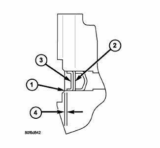
Fig. 92: Oil Gallery Cup Plug
- - CUP PLUG BORE CHAMFER
- - ORIGINAL CUP PLUG
- - NEW CUP PLUG
- - 1-2 mm
NOTE: DETERMINE WHICH CUP PLUG IS LEAKING BEFORE PERFORMING THIS PROCEDURE. IF NECESSARY, PERFORM AN ENGINE OIL LEAK INSPECTION.
Each cylinder head on a 2.7L engine has 6 external oil gallery cup plugs. It is not necessary to remove the original cup plug to install a new cup plug (3). The cup plug bore is deep enough to allow for two plugs. If it becomes necessary to service an oil gallery cup plug, perform the Repair Procedure.
NOTE: INSPECT THE CUP PLUG BORE IN QUESTION FOR THE PRESENCE OF TWO CUP PLUGS. IF THE CUP PLUG FLANGE IS JUST INSIDE (1-2 MM) THE CHAMFERED EDGE OF THE BORE TWO CUP PLUGS ARE ALREADY IN PLACE AND THE CYLINDER HEAD CANNOT BE REPAIRED.
Repair Procedure
1. Remove component(s) necessary to gain access to the oil gallery cup plug requiring service.
NOTE: SOME OF THE OIL GALLERY CUP PLUGS ARE SERVICEABLE WITH THE HEAD INSTALLED ON THE ENGINE AND THE ENGINE IN THE VEHICLE, WHILE OTHERS REQUIRE REMOVING THE AFFECTED CYLINDER HEAD FROM THE ENGINE. IN EITHER CASE ONLY REPLACE THE CUP PLUG REQUIRING SERVICE.
2. Clean the cup plug bore with brake cleaner and compressed air. It is not necessary to remove the existing cup plug.
3. Lightly coat the new cup plug with sealer; p/n 04318083.
4. Using an appropriate installation tool drive the new cup plug into the bore until the flanged edge of the plug is just inside (1-2 mm) the chamfered edge of the bore.
5. Allow the sealant to cure for at least 20 minutes.
6. Assemble any components removed in step # 1 as necessary.
 Description, Diagnosis and Testing
DESCRIPTION
Fig. 91: Cylinder Head, Valves & Springs
- VALVE KEEPER
- SPRING RETAINER
- VALVE KEEPER
- VALVE SPRING-EXHAUST
- SPRING RETAINER
- VALVE STEM SEAL
- VALVE-EXHAUST
...
 Removal
Fig. 93: Accessory Drive Belt System - 2.7L
- GENERATOR
- IDLER/TENSIONER
1. Perform fuel pressure release procedure before attempting any repairs.
2. Disconnect negative cable from rem ...
See also:
Damper, vibration
Removal
Fig. 196: Vibration Damper - Removal
- SPECIAL TOOL 8454 PULLER
- SPECIAL TOOL 8194 INSERT
1. Disconnect negative battery cable.
2. Remove right front wheel and belt splash shie ...
Removal, Installation
REMOVAL
1. Remove transmission and torque converter from vehicle.
2. Place a suitable drain pan under the converter housing end of the
transmission.
CAUTION: Verify that transmission is ...
Diagnosis and testing
BATTERY
The battery must be completely charged and the terminals should be properly
cleaned and inspected before
diagnostic procedures are performed. See Cleaning for the proper battery
cleaning ...
