Dodge Journey: Removal
LEFT-HAND-DRIVE
1. Disconnect and isolate the battery negative cable from its post on the battery.
2. If equipped, remove the silencer pad below the steering column opening cover.
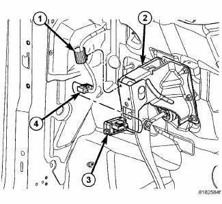
Fig. 132: STOP LAMP SWITCH WIRING CONNECTOR
3. Disconnect the wiring connector (4) at the stop lamp switch (3).
4. Remove the stop lamp switch wiring routing clip (1) from the brake pedal bracket (2).
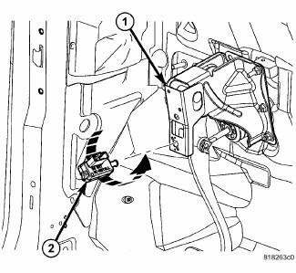
Fig. 133: STOP LAMP SWITCH REMOVAL
5. Remove the stop lamp switch (2).Do not reuse the stop lamp switch on vehicles built prior to July 21, 2008.
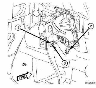
Fig. 134: BRAKE PEDAL CLIP
6. Remove the retaining clip (2) securing the power brake booster push rod (1) to the brake pedal. To do so, position a small screwdriver under the center tang of the retaining clip, then rotate the screwdriver enough to allow the retaining clip tang to pass over the end of the brake pedal pin (3). Remove and discard the clip. Do not reuse the clip.
7. Slide the booster push rod (1) off the brake pedal pin (3).
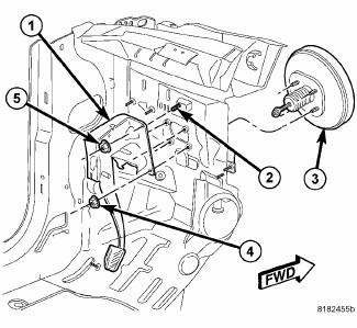
Fig. 135: PEDAL AND BOOSTER MOUNTING - LHD
8. Remove the four nuts (4) attaching the brake pedal (1) (and power brake booster) to the dash panel.
9. Remove the remaining nut (5) attaching the brake pedal (1) to the dash panel.
10. Remove the brake pedal (1).
RIGHT-HAND-DRIVE
1. Disconnect and isolate the battery negative cable from its post on the battery.
2. If equipped, remove the silencer pad below the steering column opening cover.
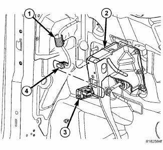
Fig. 136: STOP LAMP SWITCH WIRING CONNECTOR
3. Disconnect the wiring connector (4) at the stop lamp switch (3).
4. Remove the stop lamp switch wiring routing clip (1) from the brake pedal bracket (2).
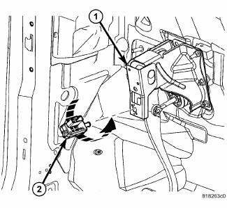
Fig. 137: STOP LAMP SWITCH REMOVAL
5. Remove the stop lamp switch (2).Do not reuse the stop lamp switch on vehicles built prior to July 21, 2008.
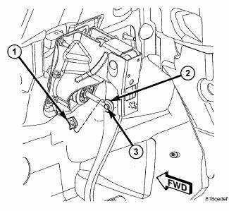
Fig. 138: BRAKE PEDAL CLIP - RHD
6. Remove the retaining clip (1) securing the power brake booster push rod (2) to the brake pedal. To do so, position a small screwdriver under the center tang of the retaining clip, then rotate the screwdriver enough to allow the retaining clip tang to pass over the end of the brake pedal pin (3). Remove and discard the clip. Do not reuse the clip.
7. Slide the booster push rod (2) off the brake pedal pin (3).
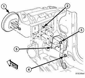
Fig. 139: PEDAL AND BOOSTER MOUNTING - RHD
8. Remove the four nuts (4) attaching the brake pedal (5) (and power brake booster) to the dash panel.
9. Remove the remaining nut (3) attaching the brake pedal (5) to the dash panel.
10. Remove the brake pedal (5).
 Installation
LEFT-HAND-DRIVE
Fig. 140: PEDAL AND BOOSTER MOUNTING - LHD
1. Carefully install the brake pedal and bracket assembly (1) in the vehicle
lining up the bracket with the
power brake booster mounti ...
See also:
Switch, headlamp leveling, export
DESCRIPTION
Fig. 45: Identifying Park Assist Switch
The headlamp leveling switch (3) is used only on vehicles manufactured for
certain export markets where the
headlamp leveling system is requi ...
Diagnosis and Testing
CLUTCH - FIXED DISPLACEMENT A/C COMPRESSOR
The compressor clutch coil electrical circuit for the Denso 10SR15 and 10SR17
fixed displacement A/C
compressors is controlled by the powertrain control ...
CARGO AREA FEATURES
Rechargeable Flashlight — If Equipped
The rechargeable LED flashlight stores in its charging
station in the left rear quarter trim panel. To remove it,
press on the indent on the side of the flas ...

