Dodge Journey: Removal
LEFT-HAND-DRIVE
CAUTION: The vacuum in the power brake booster must be depleted before removing the master cylinder to avoid damaging the master cylinder and to prevent inhalation of the o-ring or any other contamination into the booster. The preferred method is to pump the brake pedal while the engine is not running until the brake pedal becomes firm. An alternative method is to remove and immediately reinstall the check valve located on the booster. If the check valve is removed, special care should be taken to ensure that the grommet is not damaged and remains seated, the check valve is dry and free of debris, and that contaminates cannot be ingested during removal.
1. With the engine not running, pump the brake pedal 4-5 strokes until the pedal feel is firm.
2. Disconnect the negative (ground) cable from the battery and isolate the cable.
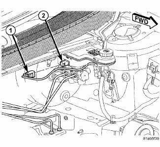
Fig. 90: BRAKE FLUID LEVEL SWITCH CONNECTOR
3. Disconnect the wiring harness connector (1) from the brake fluid level switch (2) in the master cylinder brake fluid reservoir.
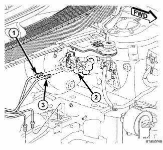
Fig. 91: PRIMARY AND SECONDARY BRAKE TUBES
4. Disconnect the primary (1) and secondary (3) brake tubes at the master cylinder (2) outlet ports. Install plugs at all of the open brake tube outlets on the master cylinder.
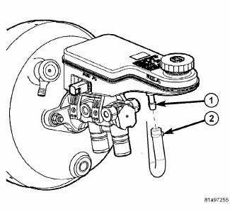
Fig. 92: CLUTCH ACTUATOR HOSE AT MASTER CYLINDER
5. If equipped with a manual transaxle, remove the clamp and slide the clutch actuator hose (2) off the reservoir port (1).
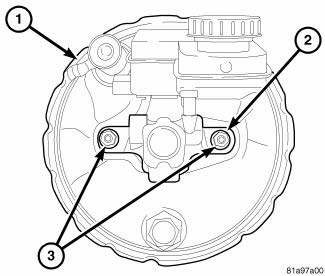
Fig. 93: MASTER CYLINDER MOUNTING NUTS
6. Clean the area around where the master cylinder (2) attaches to the power brake booster (1) using a suitable brake cleaner such as Mopar Brake Parts Cleaner or an equivalent.
7. Remove the two nuts (3) attaching the master cylinder (2) to the power brake booster (1).
8. Slide the master cylinder straight out of the power brake booster.
RIGHT-HAND-DRIVE
CAUTION: The vacuum in the power brake booster must be depleted before removing the master cylinder to avoid damaging the master cylinder and to prevent inhalation of the o-ring or any other contamination into the booster. The preferred method is to pump the brake pedal while the engine is not running until the brake pedal becomes firm. An alternative method is to remove and immediately reinstall the check valve located on the booster. If the check valve is removed, special care should be taken to ensure that the grommet is not damaged and remains seated, the check valve is dry and free of debris, and that contaminates cannot be ingested during removal.
1. With the engine not running, pump the brake pedal 4-5 strokes until the pedal feel is firm.
2. Disconnect the negative (ground) cable from the battery and isolate the cable.
3. Remove the engine appearance cover.

Fig. 94: CLUTCH ACTUATOR HOSE AT MASTER CYLINDER
4. If equipped with a manual transaxle, remove the clamp and slide the clutch actuator hose (2) off the reservoir port (1).
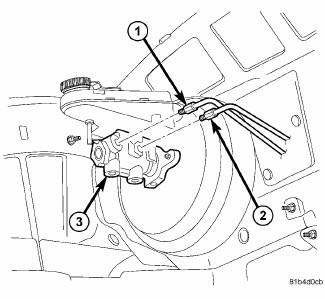
Fig. 95: PRIMARY AND SECONDARY BRAKE TUBES - RHD
5. Disconnect the primary (2) and secondary (1) brake tubes at the master cylinder outlet ports. Install plugs at both of the open brake tube outlets on the master cylinder (3).

Fig. 96: MASTER CYLINDER MOUNTING NUTS
6. Clean the area around where the master cylinder (2) attaches to the power brake booster (1) using a suitable brake cleaner such as Mopar Brake Parts Cleaner or an equivalent.
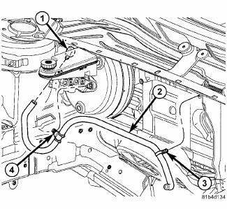
Fig. 97: VACUUM HOSE AT BOOSTER - RHD
7. Remove the booster vacuum hose routing clip (4) from the master cylinder mounting stud.

Fig. 98: MASTER CYLINDER MOUNTING NUTS
8. Remove the two nuts (3) attaching the master cylinder (2) to the power brake booster (1).
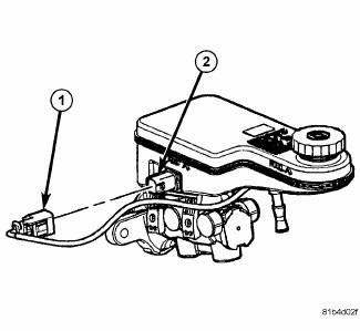
Fig. 99: BRAKE FLUID LEVEL SWITCH CONNECTOR - RHD
9. Slide the master cylinder straight out of the power brake booster, then disconnect the wiring harness connector (1) from the brake fluid level switch (2).
10. Remove the master cylinder from the engine compartment.
 Standard Procedure
MASTER CYLINDER BLEEDING
1. Clamp the master cylinder in a vise with soft-jaw caps.
Fig. 88: BLEEDING MASTER CYLINDER WITH ABS
2. Thread a Bleeder Tube (2), Special Tool 8358-1, into the primary ...
 Disassembly, Assembly
DISASSEMBLY
NOTE: If the reservoir is being replaced, the new reservoir will come
with a brake fluid
level switch installed. The old fluid switch does not need to be transferred
from
the ...
See also:
Seal, crankshaft oil, rear
Removal
Fig. 214: REAR MAIN SEAL-INSTALLED
The crankshaft rear oil seal is incorporated in the seal adapter
(2) and can not be removed from the adapter. The
crankshaft rear oil seal/seal adapte ...
Removal
LEFT-HAND-DRIVE
1. Disconnect and isolate the battery negative cable from its post on the
battery.
2. If equipped, remove the silencer pad below the steering column opening cover.
Fig. 132: S ...
Insulator, engine mount, rear
Removal
Fig. 234: Belly Pan
1. Remove throttle body air inlet hose and air cleaner housing assembly.
2. Raise the vehicle.
3. Remove the belly pan (2).
Fig. 235: Identifying Rear Mount B ...
