Dodge Journey: Manifold, exhaust, front
Removal
1. Disconnect negative battery cable.
2. Remove the engine cover.
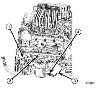
Fig. 295: Oxygen Sensors
3. Disconnect and remove oxygen sensors (2) and (4).
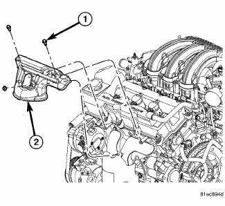
Fig. 296: Upper Maniverter Heat Shield
4. Remove the upper maniverter heat shield (2).
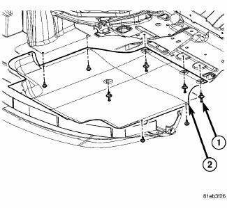
Fig. 297: Belly Pan
- - belly pan fasteners
- - belly pan
5. Remove the belly pan (2).
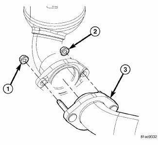
Fig. 298: Front Maniverter-To-Cross Under Fasteners
6. Remove the front maniverter-to-crossunder fasteners (1) and (2).
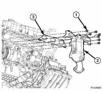
Fig. 299: Front Exhaust Maniverter Attaching Bolts
7. Remove front exhaust maniverter attaching bolts (1) and remove the front maniverter (2).
Inspection
1. Inspect exhaust manifolds for damage or cracks.
2. Check manifold flatness.
3. Inspect the exhaust manifold gasket for obvious discoloration or distortion.
4. Check distortion of the cylinder head mounting surface with a straightedge and thickness gauge.
Installation
1. Clean gasket mounting surfaces.
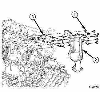
Fig. 300: Front Exhaust Maniverter Attaching Bolts
2. Install a new gasket (3), the front maniverter (2), and the front exhaust maniverter attaching bolts (1).
Tighten bolts to 23 Nm (17 ft. lb).
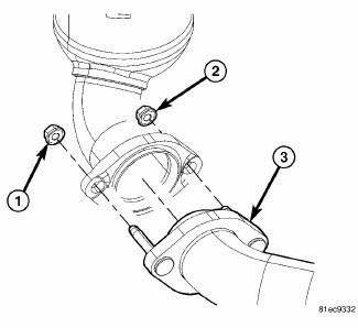
Fig. 301: Front Maniverter-To-Cross Under Fasteners
3. Install the front maniverter-to-crossunder fasteners (1) and (2). Tighten to 27 Nm (20 ft. lb.).
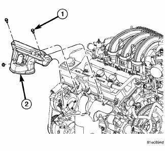
Fig. 302: Upper Maniverter Heat Shield
4. Install the upper maniverter heat shield (3) and the heat shield fasteners (1) and (2). Tighten fasteners to 12 Nm (106 in. lb.).
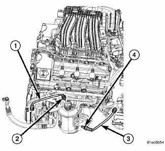
Fig. 303: Oxygen Sensors
5. Install the oxygen sensors (2) and (4). 41 Nm (30 ft. lbs.)
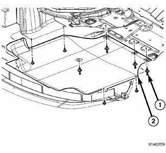
Fig. 304: Belly Pan
- - belly pan fasteners
- - belly pan
6. Install the belly pan (2).
7. Install the negative battery cable.
8. Install the engine cover.
 Manifold, exhaust, crossover
Removal
Fig. 287: Belly Pan
- belly pan fasteners
- belly pan
1. Remove the belly pan (2).
Fig. 288: Exhaust Extension Pipe
2. Remove the fasteners (1), and remove the exhaust extensio ...
 Manifold, exhaust, rear
Removal
Fig. 305: Belly Pan
- belly pan fasteners
- belly pan
1. Remove the belly pan (2).
Fig. 306: Oxygen Sensors
2. Remove the oxygen sensors (2) and (4).
Fig. 307: Exhaust Gas R ...
See also:
MIRRORS
Inside Day/Night Mirror
A two-point pivot system allows for horizontal and
vertical mirror adjustment. Adjust the mirror to center on
the view through the rear window.
Headlight glare can be reduc ...
Installation
Fig. 404: Identifying Shifter Mounting Bolts
1. Install the shifter mounting bolts and tighten to 20 N.m (15 ft. lbs.) in
the proper sequence as indicated on
drawing.
Fig. 405: Identifying Sh ...
Removal
1. Remove the engine appearance cover.
Fig. 82: Cowl Top Screen
2. Remove the two push-pins (1) securing the cowl top screen at the ends.
Remove the remaining push-pins
(2). Remove the cowl top ...
