Dodge Journey: Description, Operation
DESCRIPTION

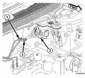
Fig. 87: PRIMARY AND SECONDARY BRAKE TUBES
All master cylinders (2) are a two-outlet design and the brake tubes from these primary and secondary outlet ports lead directly to the Integrated Control Unit (ICU) before going to each wheel brake.
All master cylinders mount to the power brake booster in the same manner.
The master cylinder body is an anodized aluminum casting. It has a machined bore to accept the master cylinder pistons and also has threaded ports with seats for hydraulic brake tube connections.
The master cylinder has the brake fluid reservoir mounted on top of it which gravity feeds brake fluid to the master cylinder when it is required. On manual transmission model vehicles the brake fluid reservoir also feeds the clutch hydraulic circuit. The reservoir is made of see-through plastic and it houses the brake fluid level switch. A removable brake fluid level switch is mounted in the right side.
OPERATION
When the brake pedal is pressed, the master cylinder primary and secondary pistons apply brake pressure through the chassis brake tubes to each brake assembly. The brake fluid reservoir supplies the brake hydraulic system with the necessary fluid to operate properly.
The master cylinder's outlet ports supply hydraulic pressure to the Integrated Control Unit (ICU) where it is distributed to the individual wheel brakes.
The master cylinder reservoir cap diaphragm is slit to allow atmospheric pressure to equalize on both sides of the diaphragm.
 Standard Procedure
MASTER CYLINDER BLEEDING
1. Clamp the master cylinder in a vise with soft-jaw caps.
Fig. 88: BLEEDING MASTER CYLINDER WITH ABS
2. Thread a Bleeder Tube (2), Special Tool 8358-1, into the primary ...
See also:
Non-monitored circuits
The PCM does not monitor all circuits, systems and conditions that could have
malfunctions causing
driveability problems. However, problems with these systems may cause the PCM to
store diagnosti ...
Installation
Fig. 164: Removing/Installing Bellhousing Upper & Lower Bolts
NOTE: If transaxle assembly is being replaced or overhauled (clutch
and/or seal
replacement), it is necessary to perform th ...
Disassembly, Assembly
DISASSEMBLY
NOTE: If the reservoir is being replaced, the new reservoir will come
with a brake fluid
level switch installed. The old fluid switch does not need to be transferred
from
the ...

