Dodge Journey: Diagnosis and Testing, Removal, Installation
DIAGNOSIS AND TESTING
INSTRUMENT CLUSTER
As a quick diagnosis, the cluster will perform a functional check of the odometer display, transmission range display and warning indicators after the ignition is switched to RUN/START. If the cluster is not receiving any bus messages, the cluster will appear non-functional and "no bus" will appear in the odometer display.
A self-test of the cluster can also be initiated by pressing and holding the odometer reset button and switching the ignition from lock to unlock. The cluster will then step through several displays for functional verification.
By pressing the trip odometer reset button while going through the self-test, you can temporarily freeze the test.
Pressing the bottom again will continue sequence. The cluster will store bus communication faults with other modules. It will also store faults for the AIRBAG and ABS lamps. During the self-diagnostics, the AIRBAG and ABS lamps are tested.
If the cluster is not functioning properly, refer to BODY article.
If the cluster is not receiving bus messages, refer to BODY article.
In order to diagnose the instrument cluster functions, a scan tool and the proper Body Diagnostic article are required.
If the diagnostic procedure determines that a replacement of an instrument cluster component is required, refer to Removal and Installation .
REMOVAL
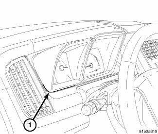
Fig. 2: Instrument Cluster
1. Disconnect and isolate the battery negative cable.
NOTE: The left hand side of the instrument cluster trim bezel is under the AC vent on the inboard side. When removing the instrument cluster trim bezel, it may be necessary to flex the AC vent slightly to relieve the bezel from under the AC vent.
2. Remove the instrument cluster trim bezel using a trim stick or equivalent and gently prying at point (1).
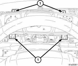
Fig. 3: Instrument Cluster
3. Remove the four attaching screws (1) from the cluster.
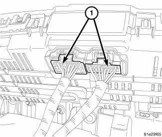
Fig. 4: Instrument Cluster & Electrical Connectors
4. Pull the cluster forward and disconnect the two electrical connectors (1).
5. Remove the cluster from the instrument panel.
INSTALLATION
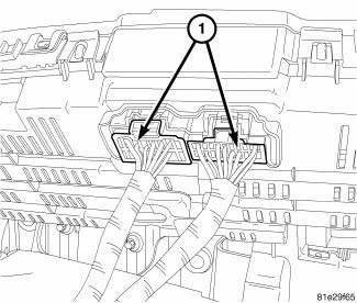
Fig. 5: Instrument Cluster & Electrical Connectors
1. Carefully slide the cluster into its location and connect the two electrical connectors (1) to the cluster.
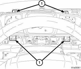
Fig. 6: Instrument Cluster
2. Position the cluster in the instrument panel and Install the four cluster attaching screws (1).
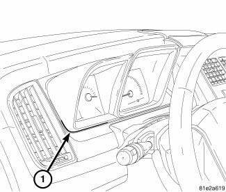
Fig. 7: Instrument Cluster
NOTE: When installing the cluster trim bezel, be sure to place the left hand side of the bezel underneath the AC vent. It may be necessary to flex the trim on the AC vent slightly to allow the cluster trim bezel locking clips secure entry into the instrument panel.
3. Install the cluster trim bezel.
4. Connect the battery negative cable.
 Indicators
Indicators are located in various positions within the CCN and are all
connected to the CCN electronic circuit
board. All indicators, except the inverter indicator (if equipped), are
controlled b ...
 Lens, instrument cluster
REMOVAL
Fig. 8: Instrument Cluster Lens Locking Tabs
1. Remove instrument cluster from vehicle. See Removal .
2. Separate the lens from the cluster by gently prying on the locking clips (1)
a ...
See also:
Disassembly
Fig. 200: Snap Ring At Output Shaft Case Bearing
1. Remove the snap ring (2) from the output shaft.
Fig. 201: Output Shaft Case Bearing And Gear
2. Use Bearing Splitter P-334 (3), Cage 8925-3 ( ...
Standard procedure
MODULE/PROGRAMMING ORDER REPLACEMENT GUIDE
MODULE PROGRAMMING
The Wireless Ignition Node (WIN) controls the Vehicle Theft Security System (VTSS),
Remote Keyless Entry
(RKE). When a Powertrain ...
Module, final drive control
DESCRIPTION
The AWD ECM (electronic control module) mounts on the driver side cowl side
panel, where it is concealed by
the instrument panel. It communicates with other systems over the high-speed ...
