
Dodge Journey: Disassembly
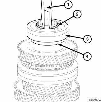
Fig. 200: Snap Ring At Output Shaft Case Bearing
1. Remove the snap ring (2) from the output shaft.
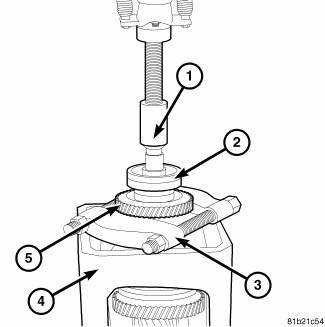
Fig. 201: Output Shaft Case Bearing And Gear
2. Use Bearing Splitter P-334 (3), Cage 8925-3 (4) and a press (1) to remove bearing (2) and third gear (5) from output shaft.
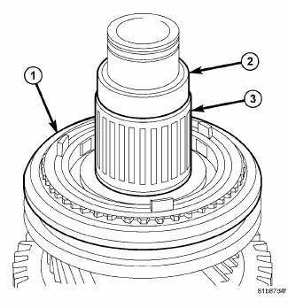
Fig. 202: Input Spacer & Bearing
3. Remove the spacer (2), ball, needle roller bearing (3) and synchronizer ring set (1).
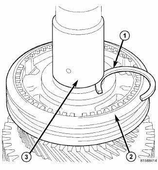
Fig. 203: Input Upper Snap Ring
4. Remove the shaft snap ring (1).
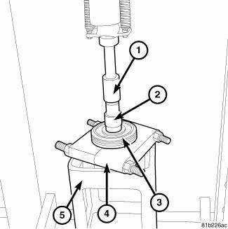
Fig. 204: Third/Fourth Gear Synchronizer & Output Shaft
5. Use Press Plate 9647 (4) and Cage 8925-3 (5) to remove third/forth gear synchronizer (3) from output shaft (2).
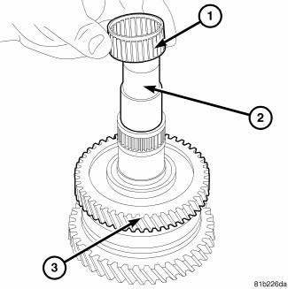
Fig. 205: Bearing & Output Shaft
6. Remove the bearing (1) from the output shaft (2).
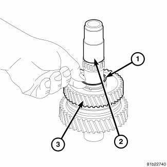
Fig. 206: Snap Ring From Output Shaft
7. Remove the spacer and snap ring (1) from output shaft (2).
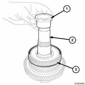
Fig. 207: Output Shaft Spacer
8. Remove the second gear inner race (1) from the output shaft (2).
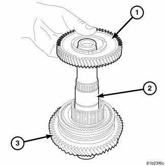
Fig. 208: Output Shaft 2nd Gear
9. Remove second gear (1) from output shaft (2).
10. Remove the needle bearing.
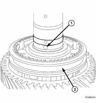
Fig. 209: Ball
11. Remove the ball (1).
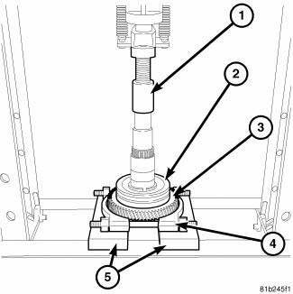
Fig. 210: First/Second Gear Synchronizer & First Gear
12. Use Bearing Splitter P-334 (4) press off the first/second gear synchronizer (3) and first gear (3).
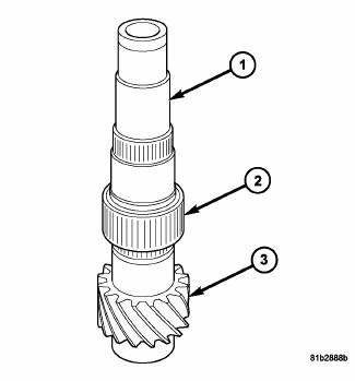
Fig. 211: First Gear Needle Bearing & Output Shaft
13. Remove the Needle bearing (2) from the output shaft (1).
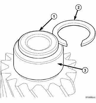
Fig. 212: Input Lower Snap Ring
14. Remove the shaft snap ring (2).
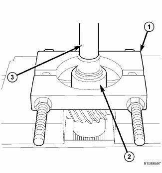
Fig. 213: Cylindrical Roller Bearing
15. Remove the cylindrical roller bearing (2) using Bearing Splitter 1130 (1) and a Press.

 Assembly
Fig. 214: First Gear Needle Bearing & Output Shaft
NOTE: Use ATF on all parts that are to be assembled in this procedure.
1. Install the first and first gear needle bearing (2) on the out ...
See also:
SUGGESTIONS FOR OBTAINING SERVICE FOR YOUR VEHICLE
Prepare For The Appointment
If you’re having warranty work done, be sure to have the
right papers with you. Take your warranty folder. All
work to be performed may not be covered by the
warranty ...
Switch, evaporative emissions system monitor
Operation
Fig. 29: Evaporative Emissions System Monitor Switch
- Intake Manifold
- Throttle Body
- Purge Solenoid
- Filter
- ESIM
- Vapor Canister
- Control Valve
- Fuel Tank
- ...
TOWING A DISABLED VEHICLE
Without The Ignition Key
Front Wheel Drive (FWD)
Special care must be taken when the vehicle is towed
with the ignition in the LOCK position. Flatbed towing is
the preferred towing method. However ...
