Dodge Journey: Control, A/C and heater, rear
DESCRIPTION
The A/C-heater controls allows the driver and front seat passenger and the intermediate seat passengers the ability to regulate air temperature as well as fan speed for the rear heating-A/C system and provides a floor outlet near the right rear door and upper air outlets at the ceiling. All controls are identified by ISO graphic symbols.
The primary controls for the rear heating-A/C system are located in the instrument panel. The rear A/C-heater control is located in the headliner and allows intermediate seat passengers to adjust rear air distribution, temperature and blower motor speed when the rear heating-A/C system primary on/off control in the instrument panel is set to the on position and the rear heater-A/C controls are NOT locked out by the driver and front seat passenger.

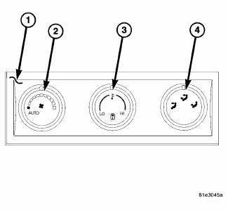
Fig. 55: ATC Tri Zone Rear Control
The rear automatic temperature control (ATC) A/C-heater control (1) contains:
- a rotary control knob for fan speed selection and turning the rear heating-A/C system off or to Auto mode (2).
- a rotary control knob for temperature control of the rear discharged air (3). An indicator lamp illuminates in the control when the rear heater-A/C controls are locked out by the driver or front seat passenger.
- a rotary control knob for mode control of the rear discharged air (4).

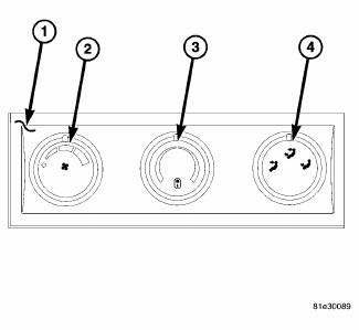
Fig. 56: Manual Temperature Control Tri Zone Rear Control
The rear manual temperature control (MTC) A/C-heater control (1) contains:
- a rotary control knob for fan speed selection and turning the rear heating-A/C system on and off (2).
- a rotary control knob for temperature control of the rear discharged air (3). An indicator lamp illuminates in the control when the rear heater-A/C controls are locked out by the driver or front seat passenger.
- a rotary control knob for mode control of the rear discharged air (4).
The rear A/C-heater control is a slave potentiometer to the front A/C-heater control and is diagnosed using a scan tool.
Prior to replacing an A/C-heater control, check for any diagnostic trouble codes (DTCs) related to the heating- A/C systems and run the calibration procedure to verify that the concern is not a system issue.
The rear A/C-heater control cannot be repaired must be replaced if inoperative or damaged. The illumination lamps are available for service replacement.
REMOVAL
NOTE: Take the proper precautions to protect the face of the rear A/C-heater control bezel from cosmetic damage during this service procedure.

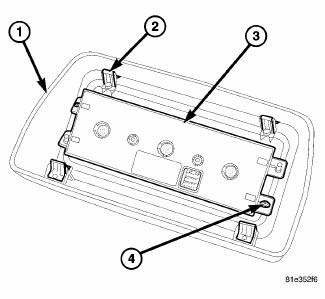
Fig. 57: Rear AC Heater Control Removal/Installation
1. Disconnect and isolate the negative battery cable.
2. Remove the rear A/C-heater control (3) and bezel (1) as an assembly from the headliner by releasing the four metal retaining tabs (2) using Trim Stick C-4755 or equivalent.
3. Disconnect the wire harness connector from the back of the rear A/C-heater control and place the control and bezel assembly on a workbench.
4. Remove the two screws (4) that secure the rear A/C-heater control to the rear control bezel and remove the control from the bezel.
INSTALLATION

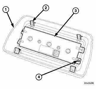
Fig. 58: Rear AC Heater Control Removal/Installation
1. Position the rear A/C-heater control (3) to the rear control bezel (1) and align the control to the two plastic guide posts on the back of the bezel.
2. Install the two screws (4) that secure the rear A/C-heater control to the rear control bezel. Tighten the screws to 1.2 N.m (10 in. lbs.).
3. Connect the wire harness connector to the back of the rear A/C-heater control and install the bezel and control as an assembly to the headliner. Make sure the four metal retaining tabs (2) are fully engaged.
4. Reconnect the negative battery cable.
5. Initiate the Actuator Calibration function using a scan tool.
 Actuator, mode door, rear
DESCRIPTION
Fig. 51: Rear Actuator Description
The mode door actuator (1) for the rear heater-A/C system is a reversible, 12
volt direct current (DC), servo
motor. The rear mode door actuator i ...
 Module, power, rear blower motor
DESCRIPTION
Fig. 59: Rear Blower Power Module Description
A blower motor power module is used on this model when equipped with the
automatic temperature control
(ATC) rear heating-A/C system. M ...
See also:
Diagnosis and Testing, Removal, Installation
DIAGNOSIS AND TESTING
INSTRUMENT CLUSTER
As a quick diagnosis, the cluster will perform a functional check of the
odometer display, transmission range
display and warning indicators after the ign ...
JUMP-STARTING
If your vehicle has a discharged battery it can be jumpstarted
using a set of jumper cables and a battery in
another vehicle or by using a portable battery booster
pack. Jump-starting can be danger ...
EMISSIONS CONTROL SYSTEM MAINTENANCE
The Scheduled Maintenance services listed in bold type,
must be done at the times or mileages specified to ensure
the continued proper functioning of the Emissions Control
System. These, and all ot ...
