Dodge Journey: Sensor, ambient temperature
DESCRIPTION
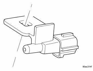
Fig. 33: Identifying Ambient Air Temperature Sensor
The ambient air temperature sensor is a variable resistor that monitors the air temperature outside of the vehicle.
The ATC system uses the sensor data to maintain optimum cabin temperature levels. The ambient air temperature sensor is mounted inside the front fascia.
OPERATION
The ambient air temperature sensor is a variable resistor that operates on a 5-volt reference signal sent by the Totally Integrated Power Module (TIPM). The ambient air temperature sensor is connected to the TIPM through a two-wire lead and connector of the vehicle wire harness. The ambient air temperature sensor changes its internal resistance in response to changes in the outside air temperature, which either increases or decreases the reference signal voltage read by the TIPM. The TIPM converts and broadcasts the sensor data over the Controller Area Network (CAN) IHS bus, where it is read by the ATC A/C-heater control, Powertrain Control Module (PCM) and other vehicle control modules.
The ambient air temperature sensor is diagnosed using a scan tool.
The ambient air temperature sensor cannot be adjusted or repaired and must be replaced if inoperative or damaged.
 Resistor, blower motor, front
DESCRIPTION
Fig. 30: Blower Motor Resistor - Description
A blower motor resistor is used on vehicles equipped with the manual
temperature control (MTC) heating-A/C
system. Vehicles equipped wit ...
 Sensor, evaporator temperature
DESCRIPTION
Fig. 34: Evaporator Temperature Sensor-Description
The evaporator temperature sensor measures the temperature of the conditioned
air downstream of the A/C
evaporator. The evaporator ...
See also:
Switch, hazard warning
DESCRIPTION
Fig. 44: Instrument Panel Switch Pod
The hazard switch (3) is integral to the instrument panel switch pod (1),
which is secured to the instrument
panel center bezel just above the h ...
Description, Operation
DESCRIPTION
Fig. 284: Rear Evaporator Description
The rear A/C evaporator (4) is located within the rear heater-A/C housing,
behind the right interior quarter panel
trim. The rear A/C evaporato ...
Installation
CLUTCH - FIXED DISPLACEMENT A/C COMPRESSOR
NOTE: Typical A/C compressor and clutch assembly shown in
illustrations.
Fig. 214: Clutch Coil & Snap Ring
1. Align the dowel pin on the bac ...
