Dodge Journey: Installation
2.4L
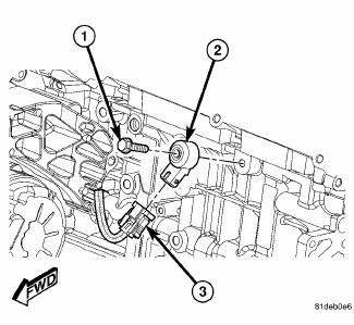
Fig. 52: 2.4L Knock Sensor
CAUTION: Always torque knock sensors to the correct torque specification. Over or under tightening effects knock sensor performance. Ensure the electrical connector orientation is at the sic O'clock position to the engine block.
1. Install knock sensor (2) and bolt (1) to engine block. Tighten bolt to 22 N.m (195 in. lbs.).
2. Connect electrical connector (3) to knock sensor (2).
3. Connect negative battery cable, tighten nut to 4.5 N.m (40 in. lbs.).
2.7L
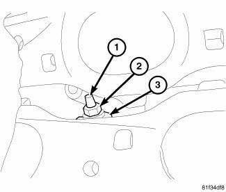
Fig. 53: Knock Sensor 2.7L
- - Stud
- - Nut
- - Knock Sensor
CAUTION: Over or under tightening effects knock sensor performance resulting in possible improper spark control.
1. Install knock sensor (3) and nut (2) onto stud (1).
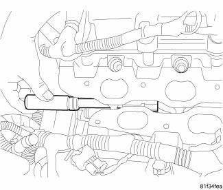
Fig. 54: Tighten Knock Sensor Nut
2. Tighten knock sensor nut to 15 N.m (11 ft. lbs.).
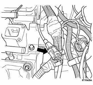
Fig. 55: Knock Sensor Connector
3. Attach electrical connector to knock sensor.
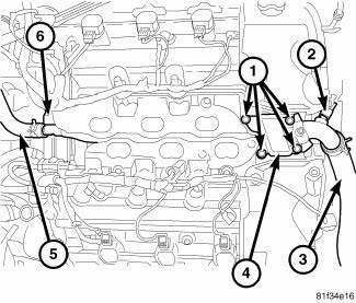
Fig. 56: Water Housing Outlet Tube 2.7L
- - Bolts
- - Coolant Temp Sensor Connector
- - Radiator Upper Hose
- - Water Housing Outlet Tube
- - Heater Hose
- - Retaining Clip
4. Position the water housing outlet tube (4) to the cylinder heads and loosely install four bolts (1).
5. Attach water housing outlet tube (4) to the retaining clip (6) at rear of engine.
6. Tighten the four bolts (1) to 3 N.m (30 in. lbs.).
7. Connect electrical connector (2) to the coolant temperature sensor.
8. Install heater hose (5) to water housing outlet tube (4) at rear of engine.
9. Install radiator upper hose (3) to water housing outlet tube (4).
10. Install intake manifold.
11. Connect negative battery cable, tighten nut to 5 N.m (45 in. lbs.).
12. Fill cooling system.
13. Operate engine until it reaches normal operating temperature. Check cooling system for correct fluid levels.
3.5L
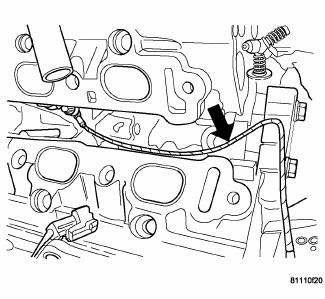
Fig. 57: Knock Sensor Wire Route
CAUTION: Always use the specified torque when installing the knock sensor bolt.
Over or under tightening the sensor mounting bolt will affect knock sensor performance, possibly causing improper spark control.
1. Install knock sensor. Tighten knock sensor to 20 N.m (15 ft. lbs.).
2. Route the knock sensor wire in the proper location.
3. Install upper intake manifold.
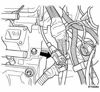
Fig. 58: Knock Sensor Connector
4. Connect the electrical connector.
5. Connect the negative battery cable.
 Removal
2.4L
Fig. 45: Locating Knock Sensor
The knock sensor bolts into the side of the cylinder block in front of the
starter under the intake manifold.
1. Disconnect and isolate negative battery ca ...
 Spark plug
...
See also:
Removal
FOOT OPERATED PARKING BRAKE LEVER
1. Release the parking brake.
2. Raise and support the vehicle.
3. Manually release the parking brake cable tension.
4. Push the front cable strand into ...
Description
Fig. 1: Muffler/Exhaust Pipe Assembly - Single Tail Pipe
- INSULATOR
- MUFFLER/EXHAUST PIPE ASSEMBLY
- BAND CLAMP
The exhaust system on the 2.4L and 2.7L engine models consists of a front ...
Transducer, A/C pressure
DESCRIPTION
Fig. 44: A/C Pressure Transducer
- A/C PRESSURE TRANSDUCER
The A/C pressure transducer (1) is a switch that is installed on a fitting
located on the A/C liquid line at the righ ...
