
Dodge Journey: Removal
DIESEL PARTICULATE FILTER
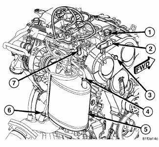
Fig. 8: DPF Components
- - ELECTRICAL CONNECTOR
- - PRESSURE DIFFERENTIAL SENSOR
- - MOUNTING BOLT
- - UPSTREAM PRESSURE TUBE
- - DPF
- - DOWNSTREAM PRESSURE TUBE
- - TUBING
1. Disconnect negative battery cable.
2. Remove the engine cover.
3. Remove the windshield wiper arm linkage.
4. Remove the eight bolts from the strut tower brace.
5. Remove the HVAC air intake box assembly.
6. Remove the differential pressure sensor tube bracket at the diesel particulate filter (DPF) (5).
7. Remove the upper DPF (5) heat shield mounting bolts.
8. Remove the right side rear engine harness bracket.
9. Disconnect the temperature sensor electrical connectors.
10. Remove the upper temperature sensor from the DPF (5).
11. Disconnect the oxygen sensor electrical connector at the DPF (5).
12. Remove the oxygen sensor from top of DPF (5).
13. Detach the lower temperature sensor wires from their retainer.
14. Remove the upper pressure differential tubing (4) from top of DPF (5).
15. Remove the DPF (5) to turbocharger clamp and gasket.
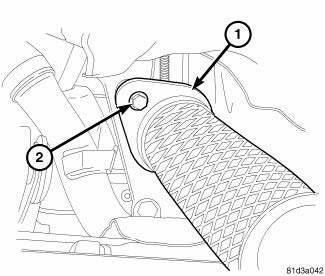
Fig. 9: Removing/Installing Diesel Particulate Filter To Exhaust Pipe
Mounting Bolts
- - FLANGE
- - BOLT
16. Raise and support the vehicle.
17. Remove the lower engine splash shield.
18. Remove the lower DPF (5) heat shield mounting bolts.
19. Remove the DPF heat shield.
20. Remove the exhaust pipe to DPF mounting bolts (2).
21. Remove the exhaust pipe from the muffler and tailpipe assembly.
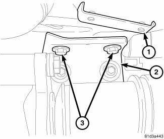
Fig. 10: Removing/Installing Diesel Particulate Filter To Axle Bracket Bolts
- - DPF
- - AXLE SUPPORT BRACKET
- - DPF TO AXLE SUPPORT BRACKET BOLTS
22. Remove the lower pressure differential tubing from the DPF.
23. Remove the exhaust manifold temperature sensor.
24. Remove the DPF (1) to axle support bracket bolts (3)
25. Lower the vehicle.
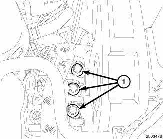
Fig. 11: Engine Support Bracket Bolts
26. Loosen the three bolts (1) at the right engine support bracket. Do not remove the engine support bracket bolts.
27. Remove the DPF and DPF to turbocharger gasket from vehicle.
 Description, Operation
DESCRIPTION
A diesel particulate filter (DPF) is installed for exhaust gas
after-treatment. The DPF filters, stores and burns
particulate matter (soot) that is generated during the combustion proc ...
 Installation
DIESEL PARTICULATE FILTER
Fig. 12: Engine Support Bracket Bolts
1. Position the DPF and turbocharger gasket into the vehicle. Do not tighten
at this time
2. Tighten the three bolts (1) at the ...
See also:
Disassembly
Fig. 314: Removing/Installing Differential Cover Bolts
- DIFFERENTIAL COVER BOLTS
- DIFFERENTIAL COVER
NOTE: The transfer shaft should be removed for differential repair and
bearing t ...
Removal
LEFT-HAND-DRIVE
CAUTION: The vacuum in the power brake booster must be pumped down
before
removing the master cylinder to prevent the booster from sucking in any
contamination. This ...
Removal
WARNING: Refer to the applicable warnings and cautions for this
system before
performing the following operation. Failure to follow these instructions
may
result in serious or fat ...
