
Dodge Journey: Solenoid, exhaust gas recirculation (EGR), 2.0L Diesel
Description
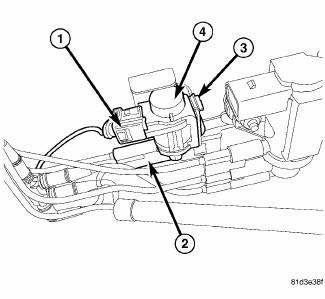
Fig. 71: Exhaust Gas Recirculation (EGR) Solenoid - 2.0L Diesel
- - EGR solenoid electrical connector
- - EGR vacuum harness
The EGR solenoid (4) is mounted to a bracket attached to the battery tray in the engine compartment. The EGR solenoid serves two different functions. One is to control vacuum bleed-off of the EGR valve. The other is to control the "on time" of the EGR valve.
Removal
1. Disconnect negative battery cable.
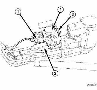
Fig. 72: Exhaust Gas Recirculation (EGR) Solenoid - 2.0L Diesel
- - EGR solenoid electrical connector
- - EGR vacuum harness
2. Disconnect the EGR solenoid electrical connector (1).
3. Disconnect the EGR vacuum harness (2) from the EGR solenoid (4) valve block.
4. Release EGR solenoid retainer clip (3) and push down to remove the EGR solenoid valve (4) from the bracket.
Installation
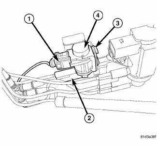
Fig. 73: Exhaust Gas Recirculation (EGR) Solenoid - 2.0L Diesel
- - EGR solenoid valve electrical connector
- - EGR vacuum harness
1. Position and install EGR solenoid valve (4) onto bracket.
2. Connect EGR vacuum harness (2) to the EGR solenoid valve (4).
3. Connect EGR solenoid valve electrical connector (1).
4. Connect negative battery cable.
 Description, Operation
DESCRIPTION
The EGR system reduces oxides of nitrogen (NOx) in the engine exhaust. This
is accomplished by allowing a
predetermined amount of hot exhaust gas to recirculate and dilute the incoming ...
 Valve, exhaust gas recirculation (EGR), 2.0L Diesel
Description
The EGR valve is mounted to the intake manifold.
Operation
The engines use Exhaust Gas Recirculation (EGR) systems. The EGR system
reduces oxides of nitrogen (NOx)
in engine exhaust ...
See also:
Relay, transmission control
DESCRIPTION
Fig. 366: Locating Transmission Control Relay
- TRANSMISSION CONTROL RELAY
- POWER DISTRIBUTION CENTER
The transmission control relay (1) is located in the Power Distribution
...
Disassembly
Fig. 229: Snap Ring At Output Shaft
1. Using Snap Ring Pliers (1) remove the snap ring (2) from the output shaft
# 2.
Fig. 230: Bearing From Cluster Shaft
2. Using a press, blocks, Bearing Sp ...
Description
The base brake system consists of the following components:
Brake pedal
Power brake booster
Master cylinder
Brake tubes and hoses
Disc brakes (four-wheel)
Brake lamp switch
Brake fluid ...
