Dodge Journey: Transmission
COOLER, TRANSMISSION OIL
Description

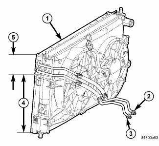
Fig. 128: TRANSMISSION OIL COOLER
- - Air Conditioning Condenser/Transmission Oil Cooler
- - Transmission Cooler Outlet
- - Transmission Cooler Inlet
- - Air Conditioning Condenser Portion
- - Transmission Cooler Portion
An external oil-to-air type automatic transmission oil cooler is mounted to the front of the radiator and is integral to the A/C condenser. The six upper tubes are used for transaxle oil cooling, and the remaining tubes below are for the A/C system.
The cooler uses tubes and rubber hoses to feed oil to and from the automatic transaxle. The replaceable inlet and outlet tubes use quick-connect type fittings. The trans oil cooler is replaced with the A/C condenser.
Operation
The oil flows from the transmission to the oil-to-air cooler. Heat is then transferred into the air.
Removal
TRANSMISSION OIL COOLER
1. The transmission oil cooler is integral to the A/C condenser. To remove the AC condenser assembly.
Cleaning
Check the AC condenser for debris on the cooling fin surfaces. Clean as necessary.
Inspection
Inspect all hoses, tubes, clamps and connections for leaks, cracks, or damage. Replace as necessary. Use only approved transmission oil cooler hoses that are molded to fit the space available.
Installation
TRANSMISSION OIL COOLER
1. The transmission oil cooler is integral to the A/C condenser. To install the AC condenser assembly.
TUBES AND HOSES, TRANSMISSION OIL COOLER
Standard Procedure
QUICK CONNECT FITTING DISASSEMBLY/ASSEMBLY
DISCONNECT

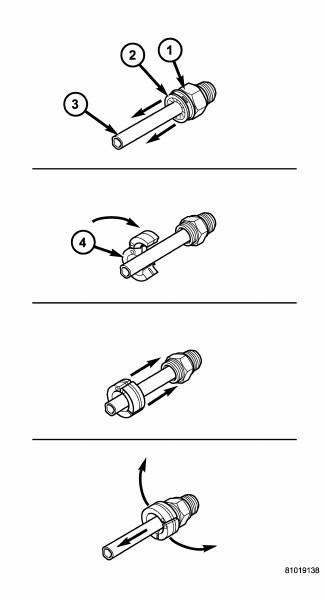
Fig. 129: OIL COOLER LINE QUICK CONNECT FITTING - DISASSEMBLY
- - QUICK CONNECT FITTING
- - DUST CAP
- - OIL COOLER LINE
- - SPECIAL TOOL 8875A
1. Remove the dust cap by pulling it straight back off of the quick connect fitting (1).
2. Place the properly sized release tool (4) onto the transmission cooler line with the fingers of the tool facing the quick connect fitting.
3. Slide the release tool down the transmission line and engage the fingers of the tool into the retaining clip.
When properly engaged in the clip, the tool will fit flush against the quick connect fitting.
4. Rotate the release tool 60º to expand the retaining clip.
5. While holding the release tool against the quick connect fitting, pull back on the transmission cooler line to remove it.
6. If thequick connect fitting is damaged or leaking at the transmission oil cooler or transmission, remove the fitting.
CONNECT

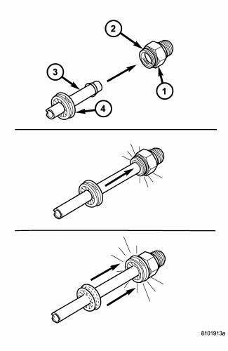
Fig. 130: OIL COOLER LINE QUICK CONNECT FITTING - ASSEMBLY
- - QUICK CONNECT FITTING
- - CLIP
- - OIL COOLER LINE
- - DUST CAP
1. If removed, install the quick connect fitting into the transmission oil cooler or the transmission. Tighten the fitting to 15 N.m (132 in. lbs.).
2. Align the cooler line (3) with the quick connect fitting while pushing straight into the fitting.
3. Push in on the transmission cooler line until a clicks heard or felt.
4. Slide the dust cap (4) down the transmission cooler line and snap it over the quick connect fitting until it is fully seated and rotates freely. The dust cap will only snap over the quick connect fitting when the transmission cooler line is properly installed.
NOTE: If the dust cap will not snap into place, repeat step 2.
 Tube, water inlet
Removal
WATER INLET TUBE
Fig. 126: WATER PUMP INLET TUBE WORLD ENGINE
- NUTS
- WATER PUMP INLET TUBE
- WATER PUMP HOUSING
The water pump inlet tube (2) connects the water pump to the co ...
See also:
Description, Operation
DESCRIPTION
Fig. 231: Receiver/Drier Description
The A/C receiver/drier (1) stores unused refrigerant, filters the
refrigerant, helps remove moisture from the
refrigerant and retains any refrig ...
Insulator, engine mount, left
Removal
Fig. 228: Belly Pan
1. Disconnect and isolate the negative battery cable.
2. Remove throttle body air inlet hose and air cleaner housing assembly.
3. Remove the belly pan (2).
...
TIRE PRESSURE MONITOR SYSTEM (TPMS)
The Tire Pressure Monitor System (TPMS) will warn the
driver of a low tire pressure based on the vehicle recommended
cold placard pressure.
The tire pressure will vary with temperature by about
1 ...

