Dodge Journey: Module, final drive control
DESCRIPTION
The AWD ECM (electronic control module) mounts on the driver side cowl side panel, where it is concealed by the instrument panel. It communicates with other systems over the high-speed CAN-C bus.
OPERATION

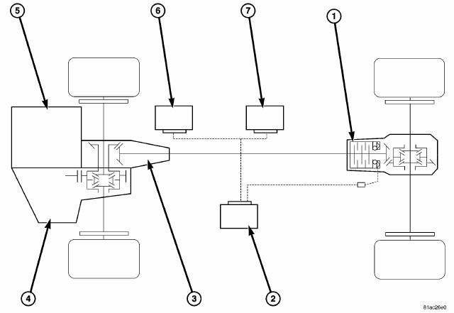
Fig. 34: AWD Outline
- - ECC
- - AWD ECU
- - PTU
- - TRANSMISSION
- - ENGINE
- - NGC
- - ABS CONTROLLER
The all-wheel-drive system requires no driver input or control. Under most driving conditions, it is passive and power is transmitted to the front wheels alone. The system functions to optimize traction and handling under the following conditions: Anticipates slip by responding to pedal position unlike all-wheel drive systems that rely on pumps or viscous fluids to transfer torque, the system requires no front-to-rear slippage for activation. This allows the system to transfer torque in response to accelerator pedal position. If the driver is asking for a lot of power, the system immediately starts clamping the Electronically Controlled Coupling (ECC), transferring a high percentage of power to the rear wheels. This avoids front wheel slippage, as power to propel the car is transmitted through all four tires. This mode of operation is called open-loop operation in that there is no feedback to affect the torque transfer.
Modulates torque to optimize traction on slippery surfaces a second, closed loop, operating mode uses feedback from the wheel-speed sensors to determine the appropriate torque transfer. When the front wheels slip, the all-wheel- drive electronic control module tells the ECC to start clamping, sending power to the rear wheels.
Attempting the same aggressive launch described above with the front wheels on ice and the rear wheels on dry pavement, the ECC sends even more torque to the rear wheels to minimize slippage and launch the vehicle.
Both modes are always active and the maximum of the two is chosen. Power to the rear wheels is modulated during lost of traction while traveling at freeway speeds; for example, hydroplaning on a puddle of water, will send very little power to the rear wheels because the controller knows at those speeds a lot of power is not needed at the rear wheels.
Prevents binding during low-speed turns a third condition, which is independent of the others, uses the ESP steering angle sensor to determine when the vehicle is turning in a tight circle. This condition causes the electronic control module to reduce torque to the rear wheels to prevent binding in the driveline. The electronic control module is always checking for this condition as well.
Influences handling at moderate speeds. The AWD system is used to influence vehicle dynamics. Other manufacturers limit AWD to aiding traction or providing off-road capability. They concentrate on launching the vehicle or going off road at speeds up to about 25 mph (40 km/hr). Above that speed range, they use it to limit wheel slip for traction. Additional ECM calibration controls torque to the rear wheels for improved handling in the 25-65 mph (40-105 km/hr) range. In this speed range, the system utilizes torque to the rear wheels during cornering with the throttle open to make the car turn more easily - make the handling more neutral. This is more readily accomplished with an electronically controlled system, than with viscous-coupling or gerotor systems that require some degree of front-to-rear slip to transfer torque to the rear wheels. Above 53 mph (113 km/hr), the control strategy provides minimal torque to the rear wheels under normal driving conditions to aid fuel economy.
Works with ESP and Traction Control the electronic control module also interfaces with the ESP and traction control systems. The interface allows the ESP system to use the ECC to help gain control of the vehicle. For this purpose, torque transmitted to the rear wheels by the ECC can be reduced. The AWD system is not traction control. It only works on situations where front-torear traction varies, for instance, front wheels on ice, rear wheels on dry pavement or climbing steep grades. AWD does not aid side-to-side traction. ESP does that through brake intervention.
REMOVAL
1. Remove the left front trim panel.
2. Remove the electrical connector.
3. Remove the mounting nuts.
4. Remove the ECC module.
INSTALLATION
1. Install ECC module into mounting studs.
2. Install mounting nuts and tighten to 8N.m (71 in. lbs.) torque.
3. Install the electrical connector.
4. Install the left front trim panel.
 Removal, Installation
REMOVAL
Fig. 30: Air Inlet Duct
1. Remove air inlet duct (3).
2. Disconnect negative battery cable.
3. Disconnect vacuum hose (1).
4. Remove air filter housing assembly (2).
Fig. 31: R ...
 Module, heated seat
DESCRIPTION
Fig. 35: Locating Heated Seat Module
The heated seat module (2) is located under the driver front seat. It has a
single electrical connector (1) and a
push pin style retainer that s ...
See also:
Description, Operation
DESCRIPTION
CAUTION: Grid lines can be damaged or scraped off with sharp
instruments. Care
should be taken in cleaning glass or removing foreign materials, decals or
stickers. Normal glass ...
Description, Operation
DESCRIPTION
Fig. 221: Condenser Description
NOTE: A/C condenser with automatic transmission cooler shown. A/C
Condenser
without cooler similar.
The A/C condenser (1) is located in the f ...
Bottle, coolant recovery
Description
NON-PRESSURE
Fig. 52: NON-PRESSURE COOLANT RECOVERY CONTAINER
- COOLANT RECOVERY CONTAINER
- OVERFLOW HOSE
- RADIATOR PRESSURE CAP
The coolant recovery system used on 2.4L e ...
