Dodge Journey: Description
Fig. 1: BG6 Manual Transaxle
- - OUTPUT SHAFT #2
- - INPUT SHAFT
- - OUTPUT SHAFT #1
- - DIFFERENTIAL
The Aisin BG 6 6-speed transaxle is a constant-mesh transaxle that is synchronized in all gear ranges.
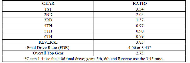
The BG 6 transaxle is a three-shaft design, as opposed to the more common two shaft configuration, to reduce overall length of the unit for easier packaging in the vehicle. The extra shaft is an output shaft. Ratios 1-4 are on one output shaft (2); ratios 5, 6 and Reverse are on the second shaft (1). Each output shaft has a different final drive ratio, which is also different from most transaxles. All ratios are synchronized.
Synchronizers are mounted on the output shafts (1, 3) to reduce the size of the transaxle. Triple-cone synchronizers on 1st through 3rd and dual-cone synchronizers 4th and 5th gears ensure that the rotating masses of gears, shafts and the clutch disc can accelerate quickly for fast, smooth shifting.
The four-plane shift mechanism is cable operated and incorporates a pull-up ring on the shift lever that must be lifted to engage Reverse. This prevents unintentional selection of Reverse when attempting to select 1st gear.
Rubber isolation of the shift system at the transaxle minimizes noise carried along the cables to the car's interior.
GEAR RATIOS

 Diagnosis and testing
COMMON PROBLEM CAUSES
The majority of transaxle malfunctions are a result of:
Insufficient lubrication
Incorrect lubricant
Misassembled or damaged internal components
Improper operation
...
See also:
Cover, structural dust
Removal
Fig. 172: Belly Pan
1. Raise and secure the vehicle on a hoist.
2. Remove the belly pan (2), if equipped.
Fig. 173: Front Engine Mount Through Bolt
3. Remove the fore/aft crossmemb ...
Removal
Fig. 25: Outer C/V Joint Seal Boot Clamps
- SMALL CLAMP
- SEALING BOOT
- OUTER CV JOINT HOUSING
- LARGE CLAMP
- INTERCONNECTING SHAFT
1. Remove halfshaft assembly requiring boot repla ...
HAZARD WARNING FLASHER
The Hazard Warning flasher
switch is located in the
instrument panel switch bank, above the climate controls.
Press the switch to turn on the Hazard Warning
flasher. When the switch is activated, ...
