Dodge Journey: Description, Operation
DESCRIPTION

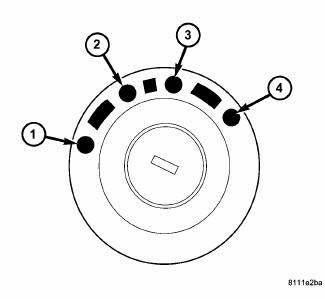
Fig. 418: Identifying Ignition Key/Switch Positions
- - LOCK
- - ACC
- - ON
- - START
The Brake Transmission Shifter/Ignition Interlock (BTSI) is a solenoid operated system that prevents the transmission gear shifter from being moved out of PARK without a driver in place.
OPERATION

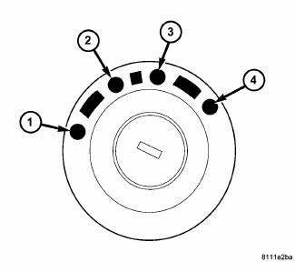
Fig. 419: Identifying Ignition Key/Switch Positions
- - LOCK
- - ACC
- - ON
- - START
The Brake Transmission Shifter/Ignition Interlock (BTSI) is engaged whenever the ignition switch is in the LOCK or ACC position. An additional electrically activated feature will prevent shifting out of the PARK position unless the brake pedal is depressed at least one-half inch. When the key is in the ON position and the brake pedal is depressed, the shifter is unlocked and will move into any position.

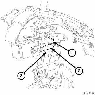
Fig. 420: Identifying Rotating Arm, Blocking Arm, & Shifter Gate Pin
When service brake pedal is not depressed the solenoid rotating arm (2) is free to rotate. The shifter gate pin (1) hits the blocking arm (3) and is prevented from moving from park.
When service brake is applied the rotating arm (2) is prevented from rotating by magnetic force within the solenoid. The shifter gate pin (1) pushes the rotating arm (2) and blocker arm (3) allowing the shifter to move out of park.
 Diagnosis and testing
SHIFT INTERLOCK SYSTEM
Fig. 421: Identifying Ignition Key/Switch Positions
- LOCK
- ACC
- ON
- START
The Shifter Response Table describes the normal operation of the
Brak ...
See also:
Sensor, speed, input
DESCRIPTION
Fig. 369: Removing/Installing Input Speed Sensor
- INPUT SPEED SENSOR
The Input Speed Sensor (1) , is a two-wire magnetic pickup device that
generates AC signals as rotation oc ...
Installation
HOUSING-AIR DISTRIBUTION
NOTE: LHD model shown in illustrations. RHD model similar.
Fig. 131: Air Distribution Housing-Removal/Installation
1. Position the air distribution housing (2) onto ...
Installation
CAUTION: Be certain to adjust the refrigerant oil level when
servicing the A/C
refrigerant system. Failure to properly adjust the refrigerant
oil level will prevent the A/C system fro ...

