Dodge Journey: Removal
WARNING: Refer to the applicable warnings and cautions for this system before performing the following operation. Failure to follow the warnings and cautions may result in possible serious or fatal injury.
NOTE: LHD model shown in illustrations. RHD model similar.
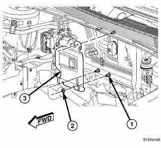
Fig. 266: Heat Shield - Unified Line
1. Disconnect and isolate the negative battery cable.
2. Recover the refrigerant from the refrigerant system.
3. If equipped with heat shield (3), remove the top nut (2) that secures the heat shield to the stud (1) located on the dash panel.
NOTE: Two slots are provided at the bottom of the heat shield to aid in heat shield removal, if equipped. Complete removal of the two bottom heat shield retaining nuts is not required.
4. If equipped, reach behind the engine and remove the two bottom nuts the that secure the heat shield to the studs located on the dash panel and remove the heat shield. Rotate and tilt the heat shield as required.
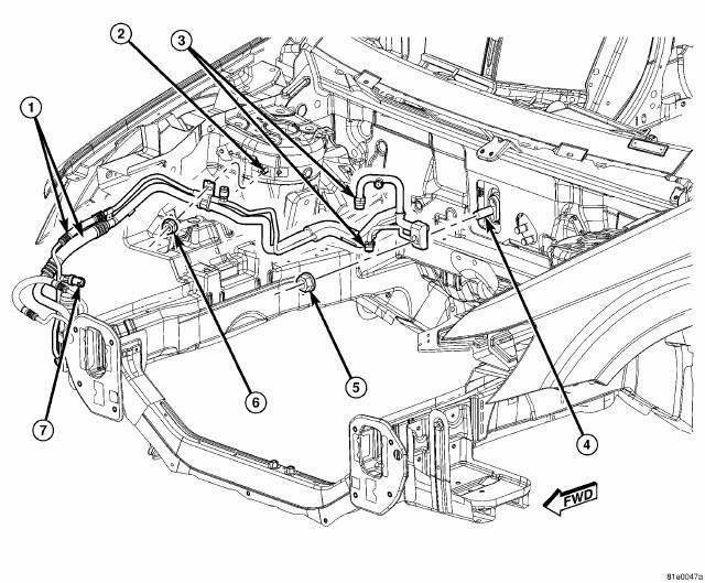
Fig. 267: Liquid & Suction Line Assembly Removal/Installation
5. Remove the nut (6) that secures the A/C liquid and suction line assembly (1) to the stud (2) located on the right front shock tower.
6. Remove the nut (5) that secures the A/C liquid and suction line assembly to the A/C expansion valve (4).
7. Disconnect the A/C liquid and suction line assembly from the A/C expansion valve, remove and discard the O-ring seals and position the refrigerant lines out of the way.
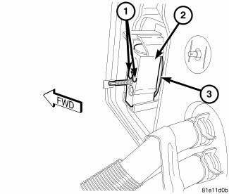
Fig. 268: Front Expansion Valve Removal/Installation
8. Remove the two bolts (1) that secure the A/C expansion valve (2) to the evaporator tube tapping block (3).
9. Remove the A/C expansion valve from the tapping block and remove and discard the O-ring seals 10. Install plugs in, or tape over the opened refrigerant fittings and all expansion valve and evaporator tube ports.
 Diagnosis and Testing
A/C EXPANSION VALVE
WARNING: Refer to the applicable warnings and cautions for this
system before
performing the following operation. Failure to follow the warnings and
cautions may ...
 Installation
CAUTION: Be certain to adjust the refrigerant oil level when
servicing the A/C
refrigerant system. Failure to properly adjust the refrigerant
oil level will prevent the A/C system fro ...
See also:
Non-monitored circuits
The PCM does not monitor all circuits, systems and conditions that could have
malfunctions causing
driveability problems. However, problems with these systems may cause the PCM to
store diagnosti ...
Module, final drive control
DESCRIPTION
The AWD ECM (electronic control module) mounts on the driver side cowl side
panel, where it is concealed by
the instrument panel. It communicates with other systems over the high-speed ...
Solenoid, pressure control
DESCRIPTION
Fig. 415: Identifying Variable Line Pressure Components
- PRESSURE CONTROL SOLENOID
- LINE PRESSURE SENSOR
- SHOULDER SCREW
- VARIABLE LINE PRESSURE HEADER
- MANUAL SHAFT
...
