Dodge Journey: Removal
WARNING: Review safety precautions and warnings in this part before performing this procedure. See Heating and Air Conditioning/Plumbing - Warning and. Failure to follow the warnings and cautions could result in possible serious or fatal injury.
NOTE: The rear A/C liquid line is only serviced as an assembly with the upper A/C suction line.
NOTE: LHD model shown in illustrations. RHD model similar.
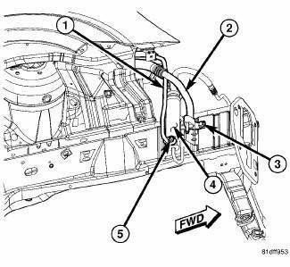
Fig. 247: Liquid Line to Receiver/Drier
NOTE: Illustration shown with front fascia and headlamp removed for clarity.
1. Disconnect and isolate the negative battery cable.
2. Recover the refrigerant from the refrigerant system.
3. Raise and support the vehicle.
4. Position the front portion of the right front wheelhouse splash shield out of the way to gain access to the A/C receiver/drier.
5. Remove the nut (5) that secures the rear section of the A/C liquid line (1) to the A/C receiver/drier (4).
6. Disconnect the rear section of the A/C liquid line from the A/C receiver/drier and remove and discard the O-ring seal and gasket.
7. Disconnect the lower portion of the A/C suction line from the A/C liquid and suction line assembly.
8. Remove the bolt (3) that secures the rear section of the A/C suction line (2) to the right front frame rail.
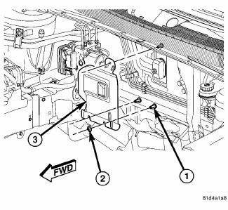
Fig. 248: Heat Shield - Unified Line
9. Lower the vehicle.
10. If equipped with heat shield (3), remove the top nut (2) that secures the heat shield to the stud (1) located on the dash panel.
NOTE: Two slots are provided at the bottom of the heat shield to aid in heat shield removal, if equipped. Complete removal of the two bottom heat shield retaining nuts is not required.
11. If equipped, reach behind the engine and remove the two bottom nuts the that secure the heat shield to the studs located on the dash panel and remove the heat shield. Rotate and tilt the heat shield as required.
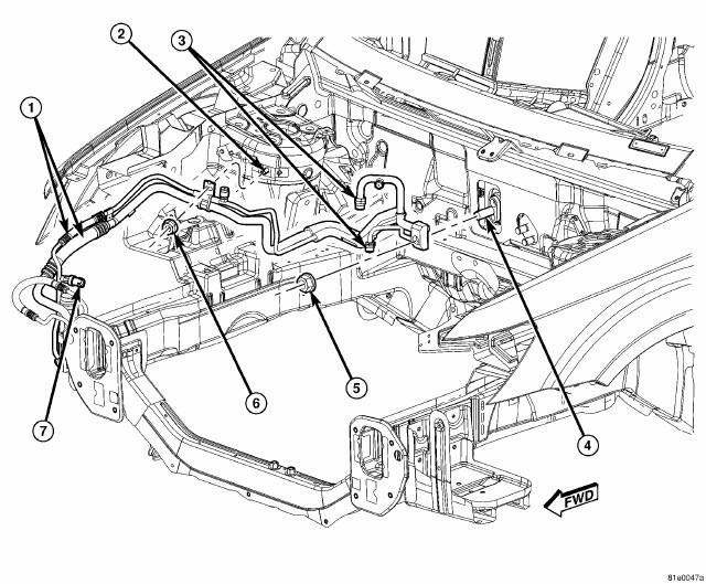
Fig. 249: Liquid & Suction Line Assembly Removal/Installation
NOTE: It is only necessary to position the engine coolant reservoir and the power steering fluid reservoir out of the way. Draining of the coolant and power steering fluid is not required.
12. Remove the engine coolant reservoir from the right side of the engine compartment and position it out of the way.
13. Remove the power steering fluid reservoir from the right front strut tower and position it out of the way.
14. If equipped with ABS, remove the ABS control module and pump assembly and position the brake lines out of the way as necessary.
15. Disconnect the wire harness connector from the A/C pressure transducer (7) located on the A/C liquid line and remove the transducer if required.
16. If equipped with rear A/C, disconnect the rear A/C extension lines from the fittings (3) located on the A/C liquid and suction line assembly.
17. Remove the nut (6) that secures the refrigerant line retaining bracket to the stud (2) located on the right front strut tower.
18. Remove the nut (5) that secures the A/C liquid and suction line assembly (1) to the A/C expansion valve (4).
19. Disconnect the A/C liquid and suction line assembly from the A/C expansion valve and remove and discard the O-ring seals.
20. Remove the A/C liquid and suction line assembly from the engine compartment.
21. Install plugs in, or tape over all of the opened refrigerant line fittings and the expansion valve and receiver/drier ports.
 Description
Fig. 246: Liquid/Suction Line Assembly with Rear A/C
NOTE: A/C liquid and suction line assembly with rear A/C shown. Front
A/C only line
assembly similar.
The A/C liquid line is serviced ...
 Installation
CAUTION: Be certain to adjust the refrigerant oil level when
servicing the A/C
refrigerant system. Failure to properly adjust the refrigerant
oil level will prevent the A/C system fro ...
See also:
Removal, Installation
REMOVAL
WARNING: To avoid serious or fatal injury on vehicles equipped
with airbags, disable
the Supplemental Restraint System (SRS) before attempting any steering
wheel, steering co ...
Toe
Fig. 115: Steering Wheel Holding Tool
1. Center the steering wheel and lock it in place using a steering wheel
clamp.
NOTE: When setting toe, make sure to set rear toe to the preferred
spe ...
STORAGE
Instrument Panel Storage Compartment — If
Equipped
Press and release the button on the door to open it. The
door swings upward to allow easy access to the compartment.
Instrument Panel Storage ...
