Dodge Journey: Thermostat
Description
2.0L DIESEL/2.4L ENGINE
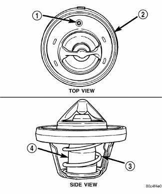
Fig. 115: THERMOSTAT
- - AIR BLEED
- - SEAL
- - RETURN SPRING
- - PELLET CHAMBER
The primary thermostat for the 2.0L diesel and 2.4L gas engines are located on the front of the water plenum in the thermostat housing/coolant inlet. The thermostat has an air bleed vent located on its flange. The air bleed vent (1) and the locator dimple on thermostat seal provide for proper positioning of thermostat in inlet housing.
The 2.4L engine has a secondary thermostat. The secondary thermostat is located in the cylinder head under the water plenum.
2.7L/3.5L
The thermostat is located on the lower left side of engine, near the front. The thermostat is on the inlet side of the water pump. It has an air bleed located in the thermostat flange. The air bleed allows internal trapped air during cooling system filling to be released.
Operation
The engine cooling thermostat is a wax pellet driven, reverse poppet choke type. The thermostat is designed to provide the fastest warm up possible by preventing leakage through it and to guarantee a minimum engine operating temperature of 88 to 93ºC (192 to 199ºF). The thermostat also will automatically reach wide open so it will not restrict flow to the radiator as temperature of the coolant rises in hot weather to around 104ºC (220º F). Above this temperature the coolant temperature is controlled by the radiator, fan, and ambient temperature, not the thermostat.
Diagnosis and Testing
ENGINE COOLANT THERMOSTAT TESTING
The thermostat is operated by a wax filled container (pellet) which is sealed. When heated coolant reaches a predetermined temperature the wax pellet expands enough to overcome the closing spring and water pump pressure, which forces the valve to open. Coolant leakage into the pellet will cause a thermostat to fail open. Do not attempt to free up a thermostat with a screwdriver.
The thermostat that opens too soon type failure mode is included in the on-board diagnosis. The check engine light will be lit by an open too soon condition. If it has failed open, a Diagnostic Trouble Code (DTC) will be set. Do not change a thermostat for lack of heater performance or temperature gauge position, unless a DTC is present. For other probable causes. Thermostat failing shut is the normal long term mode of failure, and normally, only on high mileage vehicles. The temperature gauge will indicate this.
Removal
2.4L - PRIMARY THERMOSTAT
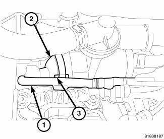
Fig. 116: PRIMARY THERMOSTAT
- - COOLANT HOSE
- - INLET HOUSING
- - BOLT
1. Partially drain cooling system.
2. Remove air filter housing.
3. Disconnect coolant hose (1) from inlet housing (2).
4. Remove inlet housing bolts (3).
5. Remove thermostat assembly, and clean sealing surfaces.
2.4L - SECONDARY THERMOSTAT
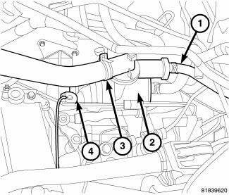
Fig. 117: SECONDARY THERMOSTAT
- - COOLANT HOSE (REAR)
- - COOLANT ADAPTER
- - RADIATOR HOSE
- - RADIATOR HOSE (FRONT)
1. Partially drain cooling system.
2. Remove air filter housing.
3. Disconnect coolant hoses (1) from rear of coolant adapter (2).
4. Remove radiator hose (3).
5. Remove radiator hose (4) from front of coolant adapter (2).
6. Remove coolant adapter mounting bolts.
7. Carefully slide coolant adapter off water pump inlet tube and remove coolant adapter (2) and secondary thermostat.
2.7L ENGINE
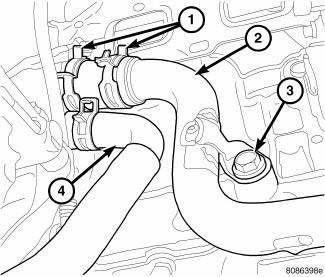
Fig. 118: THERMOSTAT AND HOUSING - 2.7L ENGINE
- - HOSE CLAMPS
- - RADIATOR HOSE TUBE
- - MOUNTING BOLT
- - RADIATOR HOSE
1. Disconnect negative cable from remote jumper terminal.
2. Drain cooling system.
3. Raise vehicle on hoist.
4. Remove right front wheel and belt splash shield.
5. Remove accessory drive belts.
6. Remove lower generator mounting bolt.
7. Lower vehicle.
8. Disconnect generator electrical connectors.
9. Disconnect AC clutch and AC pressure sensor electrical connectors. Reposition wiring harness.
10. Remove oil dipstick and tube. Plug hole in oil pan where dipstick tube mounts with water tight stopper.
WARNING: If hole for dipstick tube in oil pan is not plugged, coolant will enter oil pan. Serious engine damage can occur.
11. Remove remaining generator mounting bolts. Remove generator.
12. Remove radiator hose tube mounting bolt (3).
13. Disconnect hose clamps (1) at thermostat housing.
14. Remove thermostat housing bolts.
15. Remove thermostat and housing.
3.5L ENGINE
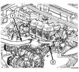
Fig. 119: THERMOSTAT HOUSING & RADIATOR HOSE
- - RADIATOR HOSE
- - THERMOSTAT HOUSING
WARNING: Do not remove pressure cap with the system hot and under pressure because serious burns from coolant can occur.
1. Disconnect negative battery cable.
2. Drain cooling system.
3. Remove engine cover.
4. Disconnect radiator upper hose from thermostat housing.
5. Remove thermostat housing bolts.
6. Remove housing, thermostat, and gasket.
2.0L DIESEL ENGINE
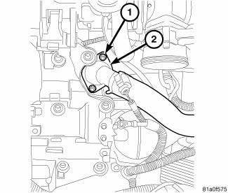
Fig. 120: THERMOSTAT HOUSING - DIESEL
- - MOUNTING BOLT
- - THERMOSTAT HOUSING
WARNING: Do not loosen the radiator cap with the cooling system hot and pressurized. Serious burns from the coolant can occur.
1. Disconnect negative battery cable.
2. Remove engine cover.
3. Drain engine coolant below thermostat level using draincock only.
4. Disconnect coolant temperature sensor electrical connector.
5. Remove coolant hoses and by-pass hose from thermostat housing.
6. Loosen accessory drive belt and reposition generator.
7. Remove thermostat housing (2) and O-ring.
8. Clean all sealing surfaces.
Installation
2.4L - PRIMARY THERMOSTAT
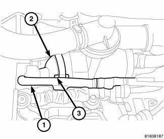
Fig. 121: PRIMARY THERMOSTAT
- - COOLANT HOSE
- - INLET HOUSING
- - BOLT
1. Position thermostat into the water plenum, aligning air bleed with the location notch on inlet housing (2).
2. Install inlet housing (2) onto coolant adapter. Tighten bolts to 9 N.m (79 in. lbs.).
3. Connect coolant hose (1).
4. Install air filter housing.
5. Fill cooling system.
2.4L - SECONDARY THERMOSTAT
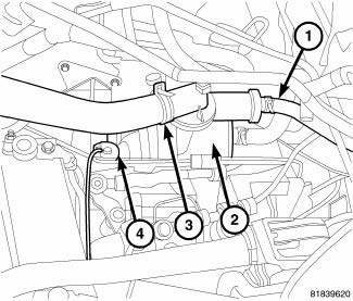
Fig. 122: SECONDARY THERMOSTAT
- - COOLANT HOSE (REAR)
- - COOLANT ADAPTER
- - RADIATOR HOSE
- - RADIATOR HOSE (FRONT)
1. Position thermostat into the cylinder head.
2. Inspect the water pump inlet tube O-rings for damage before installing the tube in the coolant adapter.
Replace O-ring as necessary.
3. Lubricate O-rings with soapy water.
4. Position coolant adapter on water pump inlet tube and cylinder head.
5. Install coolant adapter mounting bolts. Tighten bolts to 18.1 N.m (159 in. lbs.).
6. Connect front coolant hose (1).
7. Connect two rear coolant hoses (1).
8. Connect radiator hose (3).
9. Install air filter housing.
10. Fill cooling system.
2.7L ENGINE
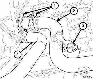
Fig. 123: THERMOSTAT AND HOUSING - 2.7L ENGINE
- - HOSE CLAMPS
- - RADIATOR HOSE TUBE
- - MOUNTING BOLT
- - RADIATOR HOSE
1. Clean gasket sealing surfaces.
NOTE: Install thermostat with the bleed valve located at the 12 o'clock position.
2. Install thermostat and gasket into the thermostat housing.
3. Install thermostat and housing to cylinder block. Tighten attaching bolts to 12 N.m (105 in. lbs.).
4. Connect hoses at thermostat housing.
5. Install generator and attaching bolts.
CAUTION: Before removing plug in oil pan, clean residual coolant from area.
6. Remove plug in oil pan and install engine oil dipstick tube.
7. Reconnect AC clutch and AC pressure sensor connectors.
8. Reconnect generator connectors.
9. Raise vehicle on hoist.
10. Install accessory drive belts.
11. Install belt splash shield and right front wheel.
12. Lower vehicle.
13. Reconnect negative battery cable.
14. Fill cooling system.
3.5L ENGINE
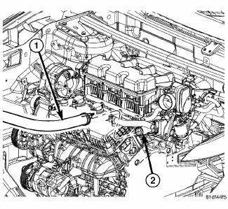
Fig. 124: THERMOSTAT HOUSING & RADIATOR HOSE
- - RADIATOR HOSE
- - THERMOSTAT HOUSING
1. Clean gasket sealing surfaces.
2. Install thermostat and gasket into thermostat housing. For ease of installation, install bolts in housing for thermostat and gasket retention.
3. Install thermostat and housing to Intake manifold. Tighten bolts to 12 N.m (105 in. lbs.).
4. Connect radiator hoses and install hose clamp.
5. Install engine cover.
6. Refill cooling system.
7. Connect negative cable.
2.0L DIESEL ENGINE
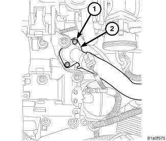
Fig. 125: THERMOSTAT HOUSING - DIESEL
- - MOUNTING BOLT
- - THERMOSTAT HOUSING
1. Clean all sealing surfaces.
2. Position and install thermostat housing (2). Tighten bolts to 9N.m (80 lbs.in.).
NOTE: Inspect condition of all clamps and hoses, replace as necessary.
3. Connect coolant temperature sensor electrical connector.
4. Install generator.
5. Install engine cover.
6. Connect negative battery cable.
7. Fill coolant system to proper level with appropriate coolant mixture. 8. Start engine and inspect for leaks.
 Sensor, coolant temperature
Description
There are two Engine Coolant Temperature (ECT) Sensors. One of the sensors
threads into the block. The other
sensor is located at the top of the coolant adapter housing. The ECT Sensor ...
 Tube, water inlet
Removal
WATER INLET TUBE
Fig. 126: WATER PUMP INLET TUBE WORLD ENGINE
- NUTS
- WATER PUMP INLET TUBE
- WATER PUMP HOUSING
The water pump inlet tube (2) connects the water pump to the co ...
See also:
Actuator, recirculation door
DESCRIPTION
Fig. 15: Blend Door Actuators
The recirculation door actuator (1) is a reversible, 12 volt direct current
(DC) servo motor, which is connected
directly to the pivot shaft lever of t ...
Removal, Installation
REMOVAL
WARNING: To protect the hands from battery acid, a suitable pair
of heavy duty
rubber gloves should be worn when removing or servicing a battery.
Safety glasses also should ...
Description
Four-wheel disc brakes are standard on this vehicle. Each disc brake assembly
consists of the following major
components:
Caliper
Caliper adapter bracket
Pads (Shoe and lining assemblies)
...
