
Dodge Journey: Body, air cleaner
REMOVAL
1. Disconnect negative battery cable.
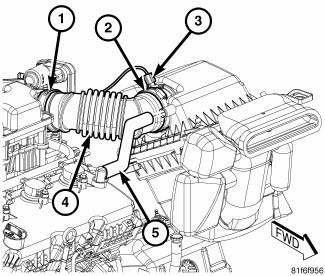
Fig. 87: Inlet Air Temperature Sensor Electrical Connector
2. Disconnect inlet air temperature sensor electrical connector (3).
3. Disconnect fresh air makeup hose (5) from the air filter box.
4. Loosen the clamp (1) from at the throttle body.
5. Remove the air inlet tube (4) from the throttle body.
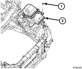
Fig. 88: Retainer From Bracket
6. Remove retainer (1) from bracket.
7. Remove the retainer that secures the air scoop to the top of the radiator core support.
8. Pull air cleaner housing (2) straight up off of locating pins.
INSTALLATION
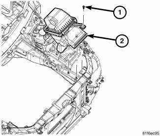
Fig. 89: Retainer From Bracket
1. Install air filter housing (2) straight down on locating pins.
2. Reposition the bracket and install the retainer (1). Tighten the retainer to 5 N.m (44 in. lbs.).
3. Install the push pin that secures the air scoop to the top of the radiator core support.
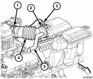
Fig. 90: Inlet Air Temperature Sensor Electrical Connector
4. Install throttle body air inlet tube (4) to the throttle body. Tighten the clamp (1).
5. Connect fresh air makeup hose (5) to the air filter housing
6. Connect inlet air temperature sensor harness connector (3).
7. Connect negative battery cable.
 Air cleaner
REMOVAL
Fig. 85: Air Filter Housing Clips
1. Disengage the air filter housing clips (1).
2. Slide the air filter housing cover (2) forward slightly to disengage tabs
from the bottom of the ai ...
 Cylinder head
...
See also:
Removal
Fig. 431: Identifying Battery Cables
- BATTERY POSITIVE CABLE
- THERMO-WRAP
- BATTERY NEGATIVE CABLE
NOTE: If valve body is replaced or reconditioned, the PCM Quick Learn
Procedure
...
Removal
BULB
Each rear lamp unit for this vehicle consists of two pieces. An outer rear
lamp unit that is secured at the rear of
each quarter panel includes bulbs for the park (or tail) lamps, the brake ( ...
Description, Operation
DESCRIPTION
Fig. 4: Rear View Camera
The Rear View Camera (RVC) (4) (also known as ParkView), is a camera on chip
device utilizing
Complementary Metal Oxide Semiconductor (CMOS) technology. CMO ...
