Dodge Journey: Installation
1. Completely retract the caliper piston back into the bore of the caliper. Use a C-clamp to retract the piston.
Place a wood block over the piston before installing the C-clamp to avoid damaging the piston.
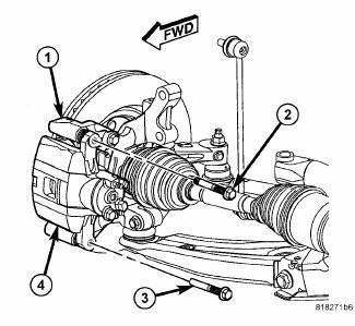
Fig. 65: CALIPER GUIDE PIN BOLTS
CAUTION: Use care when installing the caliper (4) onto the adapter bracket (1) to avoid damaging the guide pin boots.
2. Install the disc brake caliper over the brake pads on the brake caliper adapter bracket.
CAUTION: When removing or installing a caliper guide pin bolt, it is necessary to hold the guide pin stationary while turning the bolt. Hold the guide pin stationary using a wrench placed upon the pin's hex-shaped head.
3. Align the caliper guide pin bolt holes with the adapter bracket. Install the upper (2) and lower (3) caliper guide pin bolts. Tighten the guide pin bolts to 35 N.m (26 ft. lbs.).
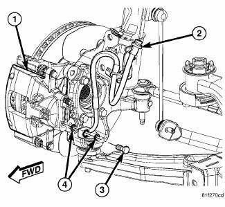
Fig. 66: BRAKE HOSE MOUNTING TO CALIPER
4. Install the banjo bolt (3) connecting the brake flex hose (2) to the brake caliper (1). Install NEW brake hose washers (4) on each side of the hose fitting as the banjo bolt is guided through the fitting. Thread the banjo bolt into the caliper and tighten it to 26 N.m (19 ft. lbs.).
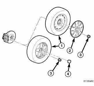
Fig. 67: TIRE AND WHEEL MOUNTING
5. Install the tire and wheel assembly (1). Refer to Tires and Wheels - Installation . Install and tighten the wheel mounting nuts (3) to 135 N.m (100 ft. lbs.).
6. Lower the vehicle.
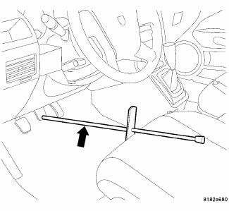
Fig. 68: BRAKE PEDAL HOLDING TOOL
7. Remove the brake pedal holding tool.
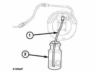
Fig. 69: BLEED HOSE SET UP
8. Bleed the caliper as necessary.
9. Road test the vehicle and make several stops to wear off any foreign material on the brakes and to seat the brake shoes.
 Disassembly, Assembly
Disassembly
NOTE: Before disassembling the brake caliper, remove it from the
vehicle.
NOTE: Before disassembling the brake caliper, clean and inspect it.
WARNING: Under no condition sh ...

See also:
Removal
FRONT
1. Raise and support the vehicle.
Fig. 163: TIRE AND WHEEL MOUNTING
2. Remove the wheel mounting nuts (3), then the tire and wheel assembly (1).
NOTE: In some cases, it may be necessary ...
Control, A/C and heater, rear
DESCRIPTION
The A/C-heater controls allows the driver and front seat passenger and the
intermediate seat passengers the
ability to regulate air temperature as well as fan speed for the rear
heat ...
Description, Diagnosis and Testing
DESCRIPTION
Fig. 38: Front Hub And Bearing Mounting
The knuckle (3) is a single casting with legs machined for attachment to the
front strut assembly on the top and
steering linkage on the trai ...
