Dodge Journey: Electrical
SWITCH, BRAKE FLUID LEVEL
Description
The brake fluid level switch (2) is mounted through the center of the fluid reservoir. The switch can be serviced separately from the master cylinder fluid reservoir.

Fig. 12: BRAKE FLUID LEVEL SWITCH CONNECTOR
The brake fluid level switch (2) is mounted through the center of the fluid reservoir. The switch can be serviced separately from the master cylinder fluid reservoir.
Removal

Fig. 13: BRAKE FLUID LEVEL SWITCH CONNECTOR
1. Remove the wiring harness connector (1) from the brake fluid level switch (2) in the master cylinder brake fluid reservoir.
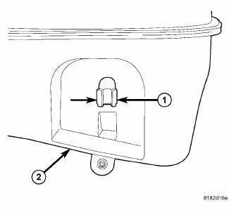
Fig. 14: LEVEL SWITCH RETAINING TABS
2. Push together the retaining tabs (1) that hold the brake fluid level switch in place in the brake fluid reservoir (2).
3. Pull the brake fluid level switch out the right side of the reservoir.
Installation

Fig. 15: LEVEL SWITCH RETAINING TABS
1. Align the brake fluid level switch with its mounting hole on the right side of the master cylinder brake fluid reservoir. Push the switch into the fluid reservoir until the switch retaining tabs (1) are expanded on the opposite side of the reservoir (2), locking it in place.
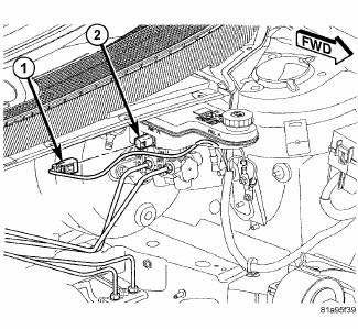
Fig. 16: BRAKE FLUID LEVEL SWITCH CONNECTOR
2. Connect the wiring harness connector (1) to the switch (2).
 Standard procedure
BASE BRAKE BLEEDING
NOTE: This bleeding procedure is only for the vehicle's base brakes
hydraulic system.
For bleeding the antilock brakes hydraulic system.
CAUTION: Before removing t ...

See also:
Removal
BATTERY HARNESS
WARNING: To protect the hands from battery acid, a suitable pair
of heavy duty
rubber gloves should be worn when removing or servicing a battery.
Safety glasses als ...
Description
Fig. 1: Exterior Lighting System
The exterior lighting system for this vehicle includes the following exterior
lamp units:
Center High Mounted Stop Lamp (3) - A standard equipment Center High ...
Indicators
Indicators are located in various positions within the CCN and are all
connected to the CCN electronic circuit
board. All indicators, except the inverter indicator (if equipped), are
controlled b ...
