Dodge Journey: Diagnosis and Testing
BRAKE LAMP SWITCH
WARNING: To avoid serious or fatal injury on vehicles equipped with airbags, disable the Supplemental Restraint System (SRS) before attempting any steering wheel, steering column, airbag, seat belt tensioner, impact sensor, or instrument panel component diagnosis or service. Disconnect and isolate the battery negative (ground) cable, then wait two minutes for the system capacitor to discharge before performing further diagnosis or service.
This is the only sure way to disable the SRS. Failure to take the proper precautions could result in accidental airbag deployment.
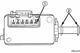
Fig. 60: Brake Lamp Switch - Early Production
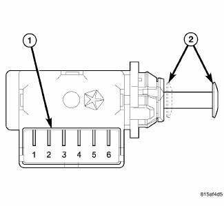
Fig. 61: Brake Lamp Switch - Late Production
1. Disconnect and isolate the battery negative cable.
CAUTION: Do not remove the Eary Production-type brake lamp switch from the mounting bracket. The self-adjusting plunger of this switch is a one time only feature. If the switch is removed from the mounting bracket, it MUST be replaced with a new switch.
2. Disconnect the wire harness connector from the brake lamp switch.
3. Using an ohmmeter, perform the continuity tests at the terminal pins (1) in the brake lamp switch connector receptacle as shown in the Brake Lamp Switch Tests table below.
|
BRAKE LAMP SWITCH TESTS |
|
| PLUNGER POSITION (2) | CONTINUITY BETWEEN |
| Released (Extended) | Pins 1 and 2 |
| Compressed (Depressed | Pins 3 and 4, 5 and 6 |
4. If the switch fails any of the continuity tests, replace the ineffective brake lamp switch as required.
 Description, Operation
DESCRIPTION
Two unique brake lamp switches are used in this vehicle, depending upon
whether the vehicle was built during
early or late production. These switches are not interchangeable and both a ...
 Removal
Two unique brake lamp switches are used in this vehicle, depending upon
whether the vehicle was built during
early or late production. These switches are not interchangeable. Both switches
are il ...
See also:
IF YOUR ENGINE OVERHEATS
In any of the following situations, you can reduce the
potential for overheating by taking the appropriate action.
• On the highways — Slow down.
• In city traffic — While stopped, put the ...
Module, heated seat
DESCRIPTION
Fig. 4: Locating Heated Seat Module
The heated seat module (2) is located under the driver front seat. It has a
single electrical connector (1) and a
push pin style retainer that se ...
REMOTE STARTING SYSTEM — IF EQUIPPED
This system uses the Remote Keyless Entry (RKE) transmitter
to start the engine conveniently from outside the
vehicle while still maintaining security. The system has a
range of approximately 300 f ...
