Dodge Journey: Frame
SPECIFICATIONS
FRAME DIMENSIONS
Frame dimensions are listed in metric scale. All dimensions are from center to center of Principal Locating Point (PLP), or from center to center of PLP and fastener location.
VEHICLE PREPARATION
Position the vehicle on a level work surface. Using screw or bottle jacks, adjust the vehicle PLP heights to the specified dimension above a level work surface. Vertical dimensions can be taken from the work surface to the locations indicated were applicable.
VEHICLE PREPARATION INDEX

Fig. 27: Frame Dimensions - Side View
Fig. 28: Frame Dimensions - Bottom View
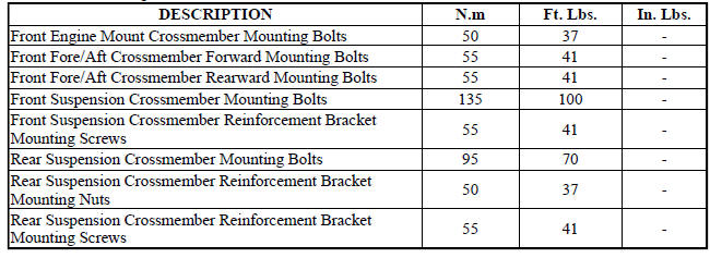
FASTENER TORQUE
 Reinforcement, bumper, rear
REMOVAL
Fig. 25: Rear Bumper Reinforcement
1. Remove rear fascia. See Removal .
2. Support bumper reinforcement (1) on a suitable lifting device.
3. Mark position of bolts (2) on frame rail ...
 Crossmember, front fore and aft
REMOVAL
1. Raise and support the vehicle.
2. If equipped, remove the engine belly pan.
Fig. 29: Removing/Installing Fore/Aft Crossmember
3. Remove the front engine mount thru-bolt (2).
Fig ...
See also:
Removal
FOOT OPERATED PARKING BRAKE LEVER
1. Release the parking brake.
2. Raise and support the vehicle.
3. Manually release the parking brake cable tension.
4. Push the front cable strand into ...
Description, Operation
DESCRIPTION
The charging system consists of:
Generator
Decoupler Pulley (2.4L and Diesel Only)
Electronic Voltage Regulator (EVR) circuitry within the Powertrain
Control Module (PCM)
Ign ...
Disassembly
Fig. 200: Snap Ring At Output Shaft Case Bearing
1. Remove the snap ring (2) from the output shaft.
Fig. 201: Output Shaft Case Bearing And Gear
2. Use Bearing Splitter P-334 (3), Cage 8925-3 ( ...
