Dodge Journey: Assembly
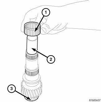
Fig. 239: Output Shaft #2 & Needle Bearing
1. Install the reverse needle bearing (1) onto the output shaft # 2 (2).

Fig. 240: Synchronizer
NOTE: Pay attention to the direction when inserting the reverse hub sleeve.
2. Install the reverse gear synchronizer onto the output shaft with (2) towards reverse gear.
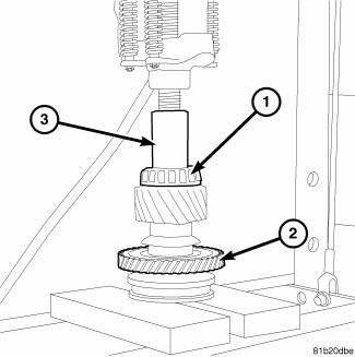
Fig. 241: Install Reverse Gear Onto Output Shaft #2
3. Install reverse gear (2) onto output shaft # 2.
4. Install reverse gear synchronizer onto output shaft using a Press (3).
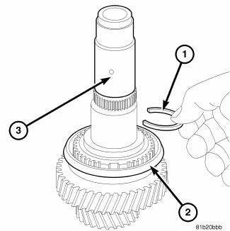
Fig. 242: Output Shaft & C-Clip
NOTE: Always use the largest snap that will fit into the grove.
5. Install the new snap ring (2) from the output shaft # 2.
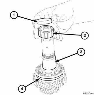
Fig. 243: #2 Bearing & Spacer
6. Install fifth needle bearing (2) and spacer (1) onto output shaft # 2 (3).
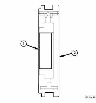
Fig. 244: Synchronizer
NOTE: Pay attention to the direction when inserting the 5th-6th hub sleeve.
7. Install the fifth gear and fifth/sixth gear synchronizer onto the output shaft with (2) towards fifth gear.
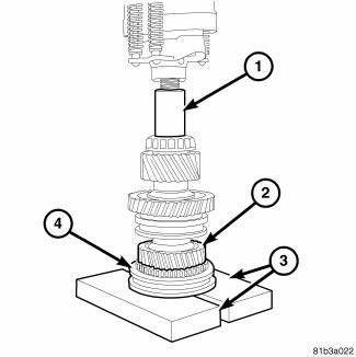
Fig. 245: 5th Gear & Synchronizer
8. Use a press to install fifth gear and fifth/sixth gear synchronizer (2).
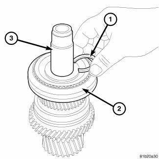
Fig. 246: Snap Ring At Output Shaft #2
NOTE: Always use the largest snap that will fit into the grove.
9. Install the new snap ring (1) from the output shaft.

Fig. 247: Sixth Gear & Bearing
10. Install spacer sixth needle bearing and sixth gear onto shaft 11. Use Sleeve C-3717 to press sixth gear and bearing (3) onto shaft.
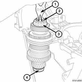
Fig. 248: Snap Ring At Output Shaft
NOTE: Always use the largest snap that will fit into the grove.
12. Install the new snap ring (2) from the output shaft.
 Disassembly
Fig. 229: Snap Ring At Output Shaft
1. Using Snap Ring Pliers (1) remove the snap ring (2) from the output shaft
# 2.
Fig. 230: Bearing From Cluster Shaft
2. Using a press, blocks, Bearing Sp ...
 Switch, backup lamp
REMOVAL
Fig. 249: Back-Up Lamp Switch
1. Disconnect battery negative cable.
2. Raise vehicle on hoist.
3. Disconnect backup lamp switch connector.
4. Remove backup lamp switch (1).
INSTA ...
See also:
Diagnosis and Testing, Removal, Installation
DIAGNOSIS AND TESTING
INSTRUMENT CLUSTER
As a quick diagnosis, the cluster will perform a functional check of the
odometer display, transmission range
display and warning indicators after the ign ...
TRAILER TOWING
In this section, you will find safety tips and information
on limits to the type of towing you can reasonably do
with your vehicle. Before towing a trailer, carefully
review this information to tow ...
Schematics and diagrams
40/41TE - WITH VARIABLE LINE PRESSURE
Fig. 181: Identifying Line Pressure - Park & Neutral
Fig. 182: Identifying Line Pressure - Reverse
Fig. 183: Identifying Line Pressure - First Gear ( ...
