Dodge Journey: Link, stabilizer bar
REMOVAL
1. Raise and support the vehicle.
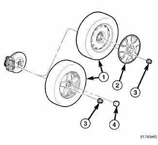
Fig. 60: TIRE AND WHEEL MOUNTING
2. Remove the wheel mounting nuts (3), then the tire and wheel assembly (1).
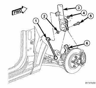
Fig. 61: Strut Mounting To Knuckle
3. While holding the stabilizer bar link (1) stud stationary, remove the nut (4) securing the link to the strut (3).
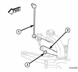
Fig. 62: Stabilizer Link Mounting To Bar
4. While holding the stabilizer bar link (1) lower stud stationary, remove the nut (3) securing the link to the stabilizer bar (2).
5. Remove the stabilizer bar link (1).
INSTALLATION
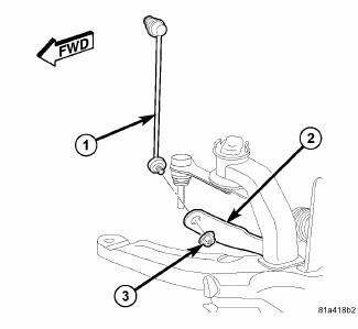
Fig. 63: Stabilizer Link Mounting To Bar
1. Attach the stabilizer bar link (1) to the stabilizer bar (2). Install and tighten the nut (3) while holding the stabilizer bar link lower stud stationary. Tighten the nut to 48 N.m (35 ft. lbs.).
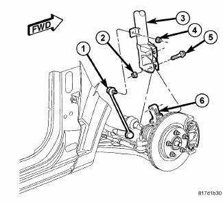
Fig. 64: Strut Mounting To Knuckle
2. Attach the stabilizer bar link (1) to the strut (3). Install and tighten the nut (4) while holding the stabilizer bar link stud stationary. Tighten the nut to 48 N.m (35 ft. lbs.).
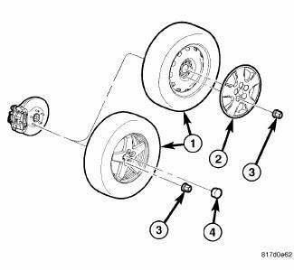
Fig. 65: TIRE AND WHEEL MOUNTING
3. Install tire and wheel assembly (1). Install and tighten wheel mounting nuts (3) to 135 N.m (100 ft. lbs.).
4. Lower the vehicle.
 Installation
Fig. 51: Front Hub And Bearing Mounting
1. If required, install the hub and bearing (1) by sliding it into the
knuckle.
2. If installing hub and bearing, install the four bolts (2) fastening t ...
See also:
Lens, instrument cluster
REMOVAL
Fig. 8: Instrument Cluster Lens Locking Tabs
1. Remove instrument cluster from vehicle. See Removal .
2. Separate the lens from the cluster by gently prying on the locking clips (1)
a ...
Removal
LEFT-HAND DRIVE
NOTE: The ABM is only separately serviceable for non-HSA (Hill Start
Assist) equipped
vehicles. Do not remove the ABM for vehicles equipped with HSA.
1. Disconnect the nega ...
Description, Operation, Diagnosis and Testing
DESCRIPTION
Fig. 1: Accessory Switch Bank Module
Vehicles with the heated seat option can be visually identified by the two
heated seat switches (1) located in the
center stack of the instrumen ...

