Dodge Journey: Description, Operation
DESCRIPTION
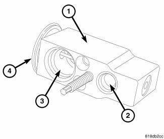
Fig. 265: A/C Expansion Valve Description KA
The A/C expansion valve controls the amount of refrigerant entering the A/C evaporator. The A/C expansion valve is of a thermostatic expansion valve (TXV) design and consists of an aluminum H-valve type body (1) with an inlet port (2), outlet port (3) and an integral thermal sensor (4).
The A/C expansion valve is located in the engine compartment at the dash panel, between the A/C refrigerant lines and the A/C evaporator.
OPERATION
The A/C expansion valve controls the high-pressure, low temperature liquid refrigerant from the A/C liquid line and converts it into a low-pressure, low-temperature mixture of liquid and gas before it enters the A/C evaporator. A mechanical sensor in the A/C expansion valve monitors the temperature and pressure of the refrigerant leaving the A/C evaporator through the A/C suction line, and adjusts the orifice size at the liquid line port to let the proper amount of refrigerant into the evaporator to meet the vehicle A/C cooling requirements.
Controlling the refrigerant flow through the A/C evaporator ensures that none of the refrigerant leaving the A/C evaporator is still in a liquid state, which could damage the A/C compressor.
NOTE: Replacement of the refrigerant line O-ring seals is required anytime a refrigerant line is disconnected from the expansion valve, or if the expansion valve is removed. Failure to replace the rubber O-ring seals may result in a refrigerant system leak.
The A/C expansion valve is factory calibrated and cannot be adjusted or repaired and must be replaced if inoperative or damaged.

 Diagnosis and Testing
A/C EXPANSION VALVE
WARNING: Refer to the applicable warnings and cautions for this
system before
performing the following operation. Failure to follow the warnings and
cautions may ...
See also:
AUTOMATIC TRANSMISSION
CAUTION:
Damage to the transmission may occur if the following
precautions are not observed:
• Shift into PARK only after the vehicle has come to
a complete stop.
• Shift into or out of REVER ...
Diagnosis and Testing, Removal, Installation
DIAGNOSIS AND TESTING
INSTRUMENT CLUSTER
As a quick diagnosis, the cluster will perform a functional check of the
odometer display, transmission range
display and warning indicators after the ign ...
Installation
Fig. 164: Removing/Installing Bellhousing Upper & Lower Bolts
NOTE: If transaxle assembly is being replaced or overhauled (clutch
and/or seal
replacement), it is necessary to perform th ...
