Dodge Journey: Duct, defroster
REMOVAL
WARNING: Disable the airbag system before attempting any steering wheel, steering column or instrument panel component diagnosis or service. Disconnect and isolate the negative battery (ground) cable, then wait two minutes for the airbag system capacitor to discharge before performing further diagnosis or service. This is the only sure way to disable the airbag system. Failure to follow these instructions may result in accidental airbag deployment and possible serious or fatal injury.
NOTE: Take the proper precautions to protect the front face of the instrument panel from cosmetic damage while performing this procedure.
NOTE: LHD model shown. RHD model similar.
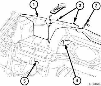
Fig. 65: Defroster Duct
1. Remove the instrument panel and place it on a workbench.
2. Remove the outboard instrument panel air outlets.
3. Remove the cover from the instrument panel.
4. Remove the driver side outboard instrument panel and demister duct assembly.
5. Disengage the two retaining clips (2) that secure the wire harness lead (3) to the top of the defroster duct (1).
6. Disconnect the defroster duct from the passenger side demister duct (4) and remove the defroster duct from the instrument panel support (5).
INSTALLATION
NOTE: Take the proper precautions to protect the front face of the instrument panel from cosmetic damage while performing this procedure.
NOTE: LHD model shown. RHD model similar.

Fig. 66: Defroster Duct
1. Position the defroster duct (1) to the top of the instrument panel support (5) and connect it to the passenger side demister duct (4).
2. Engage the two retaining clips (2) that secure the wire harness lead (3) to the top of the defroster duct.
3. Install the driver side instrument panel and demister duct assembly.
4. Install the cover onto the instrument panel support.
5. Install the outboard instrument panel air outlets.
6. Install the instrument panel.


See also:
Description, Operation
DESCRIPTION
This vehicle is equipped with a Wireless Ignition Node (WIN) (1). The WIN and
the FOB with Integrated Key
(FOBIK) are the primary components of the keyless ignition system. The only
...
Switch, oil pressure
Description
The engine oil pressure switch is located on the right side of the engine
block. The switch screws into the
engine main oil gallery. The normally closed switch provides an input throug ...
Link, stabilizer bar
REMOVAL
1. Raise and support the vehicle.
Fig. 60: TIRE AND WHEEL MOUNTING
2. Remove the wheel mounting nuts (3), then the tire and wheel assembly (1).
Fig. 61: Strut Mounting To Knuckle
3. W ...
