Dodge Journey: Sensor, ambient temperature
DESCRIPTION
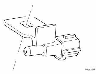
Fig. 33: Identifying Ambient Air Temperature Sensor
The ambient air temperature sensor is a variable resistor that monitors the air temperature outside of the vehicle.
The ATC system uses the sensor data to maintain optimum cabin temperature levels. The ambient air temperature sensor is mounted inside the front fascia.
OPERATION
The ambient air temperature sensor is a variable resistor that operates on a 5-volt reference signal sent by the Totally Integrated Power Module (TIPM). The ambient air temperature sensor is connected to the TIPM through a two-wire lead and connector of the vehicle wire harness. The ambient air temperature sensor changes its internal resistance in response to changes in the outside air temperature, which either increases or decreases the reference signal voltage read by the TIPM. The TIPM converts and broadcasts the sensor data over the Controller Area Network (CAN) IHS bus, where it is read by the ATC A/C-heater control, Powertrain Control Module (PCM) and other vehicle control modules.
The ambient air temperature sensor is diagnosed using a scan tool.
The ambient air temperature sensor cannot be adjusted or repaired and must be replaced if inoperative or damaged.
 Resistor, blower motor, front
DESCRIPTION
Fig. 30: Blower Motor Resistor - Description
A blower motor resistor is used on vehicles equipped with the manual
temperature control (MTC) heating-A/C
system. Vehicles equipped wit ...
 Sensor, evaporator temperature
DESCRIPTION
Fig. 34: Evaporator Temperature Sensor-Description
The evaporator temperature sensor measures the temperature of the conditioned
air downstream of the A/C
evaporator. The evaporator ...
See also:
Description
MANUAL TEMPERATURE CONTROL (MTC) SINGLE ZONE
The A/C-heater control for the front Manual Temperature Control (MTC) single
zone system allows one
temperature setting for the entire vehicle. All con ...
VOICE COMMAND — IF EQUIPPED
Voice Command can be initiated by pressing the VR
button located on the radio or
steering wheel
controls (if equipped).
Refer to “Voice Command” in the Uconnect™ Phone
User Manual located ...
Installation
Fig. 40: Seal Protector
- HALFSHAFT
- SEAL PROTECTOR
1. Install halfshaft to hub/bearing assembly. Install hub nut and washer but
do not tighten at this time.
2. Using Seal Protector 9 ...
