Dodge Journey: Solenoid, evaporative emissions purge
Operation
During the cold start warm-up period and the hot start time delay, the PCM does not energize the solenoid.
When de-energized, no vapors are purged.
The proportional purge solenoid operates at a frequency of 200 hz and is controlled by an engine controller circuit that senses the current being applied to the proportional purge solenoid and then adjusts that current to achieve the desired purge flow. The proportional purge solenoid controls the purge rate of fuel vapors from the vapor canister and fuel tank to the engine intake manifold.
Removal
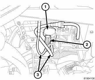
Fig. 27: PURGE SOLENOID CONNECTIONS
1. Disconnect and isolate negative battery cable at battery.
2. If equipped with 2.7L or 3.5L engine, remove the PCM.
3. Disconnect electrical connector (2) from evaporator purge solenoid (1).
4. Remove purge hose and quick connect fuel tank hose (3) from evaporator purge solenoid (1).
5. Release tab to remove evaporator purge solenoid (1) from bracket.
Installation

Fig. 28: PURGE SOLENOID CONNECTIONS
1. Install evaporator purge solenoid (1) to bracket. Make sure the tab secures the solenoid to the bracket.
2. Install quick connect fuel tank hose and purge hose (3) to evaporator purge solenoid (1).
3. Connect electrical connector (2) to evaporator purge solenoid (1).
4. If equipped with 2.7L or 3.5L engine, install the PCM.
5. Connect negative battery cable, tighten nut to 5 N.m (45 in. lbs.).
 Canister, vapor
Operation
All gasoline fueled vehicles use a maintenance free, evaporative (EVAP)
canister. Fuel tank vapors vent into the
canister. The canister temporarily holds the fuel vapors until intake man ...
 Switch, evaporative emissions system monitor
Operation
Fig. 29: Evaporative Emissions System Monitor Switch
- Intake Manifold
- Throttle Body
- Purge Solenoid
- Filter
- ESIM
- Vapor Canister
- Control Valve
- Fuel Tank
- ...
See also:
Description, Operation
DESCRIPTION
Fig. 430: Identifying Valve Body Assembly
- VALVE BODY
- T/C REGULATOR VALVE
- L/R SWITCH VALVE
- CONVERTER CLUTCH CONTROL VALVE
- MANUAL VALVE
- CONVERTER CLUTCH SWITCH V ...
Removal
Fig. 431: Identifying Battery Cables
- BATTERY POSITIVE CABLE
- THERMO-WRAP
- BATTERY NEGATIVE CABLE
NOTE: If valve body is replaced or reconditioned, the PCM Quick Learn
Procedure
...
DEALER SERVICE
Your authorized dealer has the qualified service personnel,
special tools, and equipment to perform all service
operations in an expert manner. Service Manuals are
available which include detailed ...
