Dodge Journey: Belt, serpentine, power steering
Removal
2.7L ENGINE

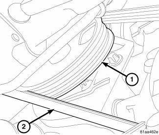
Fig. 28: STRETCH TO FIT POWER STEERING BELT REMOVAL
- - POWER STEERING PULLEY
- - STRETCH TO FIT POWER STEERING BELT
1. Raise and support the vehicle.
2. Remove RH wheelhouse splash shield.
3. Use a socket and ratchet to rotate the crankshaft clockwise.
4. While rotating the crankshaft clockwise, walk the power steering drive belt (2) off of the power steering pulley (1)
5. Remove the power steering drive belt (2).
Installation
2.7L ENGINE

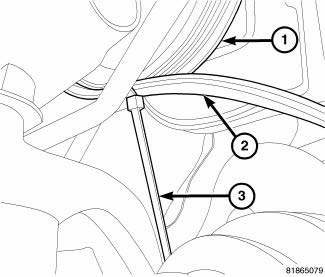
Fig. 29: POWER STEERING DRIVE BELT INSTALLATION
- - P/S PUMP PULLEY
- - POWER STEERING BELT
- - NYLON WIRE TIE
1. Position the power steering drive belt (2) on the crankshaft pulley. Make sure the belt (2) is fully seated in the crankshaft pulley grooves.
2. Position the bottom of the drive belt (2) on the bottom of the power steering pulley (1).
NOTE: Use only wire ties with nylon locks, not metal.
3. Working from the back side of the power steering pulley (1), insert a nylon wire tie (3), 7.75X1/8x0.050 in. through one of the holes in the pulley (1).
4. Tighten the wire tie to hold the drive belt (2) in position.
5. While holding the drive belt (2) to make sure it stays in position, slowly rotate the engine clockwise.
6. Once the belt is in position on the pulley (1), continue rotating the engine until the wire tie snaps (3).
7. Remove the wire tie (3) from the vehicle.
8. Install the RH wheelhouse splash shield.
 Belt, serpentine
Description
Fig. 15: ACCESSORY DRIVE BELT - WORLD ENGINE
- POWER STEERING PUMP
- ACCESSORY DRIVE BELT
- GENERATOR
- CRANKSHAFT PULLEY
- LOWER IDLER PULLEY
- CRANKSHAFT PULLEY
- WATE ...
 Pulley, idler
Removal
2.4L ENGINE
Fig. 30: ACCESSORY DRIVE BELT IDLER PULLEY - 2.4L
- UPPER PULLEY
- LOWER PULLEY
1. Remove accessory drive belt.
2. Remove upper idler pulley (1) and bolt.
3. Re ...
See also:
Frame
SPECIFICATIONS
FRAME DIMENSIONS
Frame dimensions are listed in metric scale. All dimensions are from center
to center of Principal Locating
Point (PLP), or from center to center of PLP and fasten ...
Description
The parking brake consists of the following components:
Foot-operated parking brake lever *
Cables (front, left rear, right rear)
Cable equalizer
Caliper with Integral Parking Brake (IPB)
...
Diagnosis and testing
COMMON PROBLEM CAUSES
The majority of transaxle malfunctions are a result of:
Insufficient lubrication
Incorrect lubricant
Misassembled or damaged internal components
Improper operation
...
