Dodge Journey: Installation
Fig. 40: Seal Protector
- - HALFSHAFT
- - SEAL PROTECTOR
1. Install halfshaft to hub/bearing assembly. Install hub nut and washer but do not tighten at this time.
2. Using Seal Protector 9099 (2) , install halfshaft (1) to differential assembly. Clean tool and seal area to prevent debris intrusion.
Fig. 41: Module Mounting Bolt
- - BOLT
- - DRIVELINE MODULE
3. Raise driveline module into position. Install module mounting bolt (1) .
Fig. 42: Module Mounting Bolts
- - BOLT (2)
- - DRIVELINE MODULE
4. Install remaining two module mounting bolts (2) .
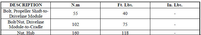
5. Torque module-to-cradle bolts to 102 N.m (75 ft. lbs.) 6. Torque the halfshaft/hub nut to 160 N.m (118 ft.lbs.).
7. Install wheel center cap.
8. Check and adjust differential fluid level.
SPECIFICATIONS

SPECIAL TOOLS
Fig. 43: Protector, 9099
 Removal
Fig. 35: Removing/Installing Halfshaft Nut
NOTE: Rear suspension and drivetrain design require this procedure to
be performed
on a "drive-on" hoist, as the front and rear suspensi ...
 Intermediate shaft, gas
REMOVAL
2.4L
1. Remove the right half shaft.
Fig. 44: Intermediate Shaft - 2.4L
2. Remove the three intermediate shaft bolts (1).
3. Remove the intermediate shaft (2).
2.7L
1. Remove the r ...
See also:
Description, Operation
DESCRIPTION
Fig. 7: Blend Door Actuators
The blend door actuators (1) for the front heating-A/C system are reversible,
12-volt direct current (DC) servo
motors. Models with the front single zon ...
Tube, exhaust gas recirculation (EGR)
Removal
2.7L - LOWER TUBE
Fig. 50: Lower Exhaust Gas Recirculation Tube - 2.7L
WARNING: The normal operating temperature of the exhaust gas
recirculate (EGR)
valve and tube is very ...
Removal
LEFT-HAND-DRIVE
CAUTION: The vacuum in the power brake booster must be depleted
before removing
the master cylinder to avoid damaging the master cylinder and to prevent
inhalation of ...
