Dodge Journey: Removal

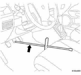
Fig. 56: BRAKE PEDAL HOLDING TOOL
1. Using a brake pedal holding tool as shown, depress the brake pedal past its first one inch (25 mm) of travel and hold it in this position. This will isolate the master cylinder from the brake hydraulic system and will not allow the brake fluid to drain out of the master cylinder reservoir when the lines are opened.
2. Raise and support the vehicle.

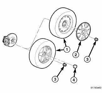
Fig. 57: TIRE AND WHEEL MOUNTING
3. Remove the wheel mounting nuts (3), then the tire and wheel assembly.

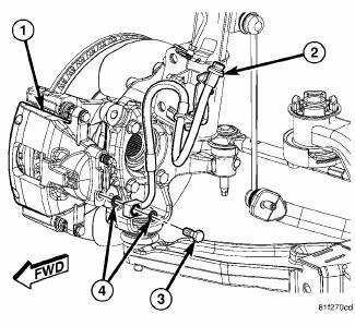
Fig. 58: BRAKE HOSE MOUNTING TO CALIPER
4. Remove the banjo bolt (3) connecting the brake flex hose (2) to the brake caliper (1). There are two washers (4) that will come off with the banjo bolt. Discard the washers. They should not be reused.

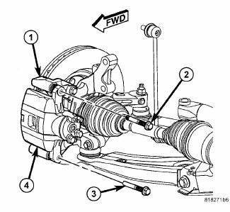
Fig. 59: CALIPER GUIDE PIN BOLTS
CAUTION: When removing or installing a caliper guide pin bolt, it is necessary to hold the guide pin stationary while turning the bolt. Hold the guide pin stationary using a wrench placed upon the pin's hex-shaped head.
5. Remove the two brake caliper guide pin bolts (2, 3).
6. Slide the disc brake caliper (4) from the disc brake adapter bracket (1) and brake pads and remove.
 Disassembly, Assembly
Disassembly
NOTE: Before disassembling the brake caliper, remove it from the
vehicle.
NOTE: Before disassembling the brake caliper, clean and inspect it.
WARNING: Under no condition sh ...
See also:
Operation, Removal
OPERATION
CAMSHAFT AND CRANKSHAFT SIGNALS
Fig. 29: 4 Cylinder Cam & Crank Signals
NOTE: The graphic represents the relationship between camshaft and
crankshaft
sensors edges with cams ...
BRAKE SYSTEM
Your vehicle is equipped with dual hydraulic
brake systems. If either of the two hydraulic
systems loses normal capability, the remaining
system will still function. However, there will
be some ...
Description
Fig. 142: Instrument Panel Outlets
There are two defroster air outlets (1) in the defroster grille (2) located
at the top of the instrument panel. The
airflow from the defroster outlets are dire ...

