Dodge Journey: Standard procedure
BASE BRAKE BLEEDING
NOTE: This bleeding procedure is only for the vehicle's base brakes hydraulic system.
For bleeding the antilock brakes hydraulic system.
CAUTION: Before removing the master cylinder reservoir cap, thoroughly clean the cap and master cylinder fluid reservoir to prevent dirt and other foreign matter from dropping into the master cylinder fluid reservoir.
NOTE: The following wheel sequence should be used when bleeding the brake hydraulic system. The use of this wheel sequence will ensure adequate removal of all trapped air from the brake hydraulic system.
- Left Rear Wheel
- Right Front Wheel
- Right Rear Wheel
- Left Front Wheel
NOTE: When bleeding the brake system, some air may be trapped in the brake lines far upstream, as much as ten feet from the bleeder screw. Therefore, it is essential to have a fast flow of a large volume of brake fluid when bleeding the brakes to ensure all the air gets out.
Pressure bleeding the brakes is recommended, although the brakes may be manually bled or pressure bled.
Refer to the appropriate following procedure.
PRESSURE BLEEDING PROCEDURE
Follow the pressure bleeder manufacturer's instructions for use of the pressure bleeding equipment.
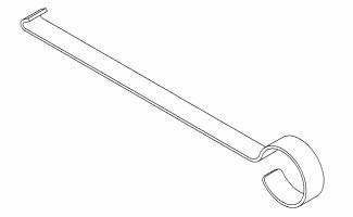
Fig. 1: BLEED HOSE SET UP
1. Install Master Cylinder Pressure Bleed Cap, Special Tool 6921, or equivalent on the master cylinder fluid reservoir. Attach the fluid hose from the pressure bleeder to the fitting on Special Tool 6921.
2. Attach a clear plastic hose (1) to the bleeder screw and feed the hose into a clear jar (2) containing enough fresh brake fluid to submerge the end of the hose.
3. Open the bleeder screw at least one full turn or more to obtain a steady stream of brake fluid.
4. After approximately 120-240 ml (4-8 ounces) of fluid have been bled through the brake circuit and an air-free flow is maintained in the clear plastic hose and jar, close the bleeder screw.
5. Repeat this procedure at all the remaining bleeder screws.
6. Check and adjust brake fluid level to the FULL mark on the reservoir.
7. Check brake pedal travel and feel. If pedal travel is excessive or if the pedal feels excessively spongy, some air may still be trapped in the system. Re-bleed the brakes as necessary including the IPB Caliper Brake Bleeding Procedure on the rear calipers as listed below.
8. Test drive the vehicle to verify the brakes are operating properly and pedal feel is correct.
MANUAL BLEEDING PROCEDURE
NOTE: To bleed the brakes manually, the aid of a helper will be required.
Fig. 2: BLEED HOSE SET UP
1. Attach a clear plastic hose (1) to the bleeder screw and feed the hose into a clear jar (2) containing enough fresh brake fluid to submerge the end of the hose.
2. Have a helper pump the brake pedal three or four times and hold it in the down position.
3. With the pedal in the down position, open the bleeder screw at least one full turn.
4. Once the brake pedal has dropped, close the bleeder screw. After the bleeder screw is closed, release the brake pedal.
5. Repeat the above steps until all trapped air is removed from that wheel circuit (usually four or five times).
6. Bleed the remaining wheel circuits in the same manner until all air is removed from the brake system.
Monitor the fluid level in the master cylinder reservoir to make sure it does not go dry.
7. Check and adjust brake fluid level to the FULL mark.
8. Check brake pedal travel and feel. If pedal travel is excessive or if the pedal feels excessively spongy, some air may still be trapped in the system. Re-bleed the brakes as necessary including the IPB Caliper Brake Bleeding Procedure on the rear calipers as listed below.
9. Test drive the vehicle to verify the brakes are operating properly and pedal feel is correct.
IPB CALIPER BRAKE BLEEDING PROCEDURE
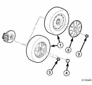
Fig. 3: TIRE AND WHEEL MOUNTING
NOTE: The following procedure is normally only necessary if a rear brake caliper has been removed and installed, or replaced.
Perform the following procedure on each rear brake caliper as necessary.
1. Raise and support vehicle.
2. Remove the wheel mounting nuts (3), then the tire and wheel assembly (1).
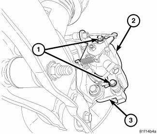
Fig. 4: REAR CALIPER MOUNTING
3. Remove the brake caliper lower guide pin bolt (1).
4. Swing the caliper assembly upward, pivoting off the upper guide pin, until clear of the adapter bracket.
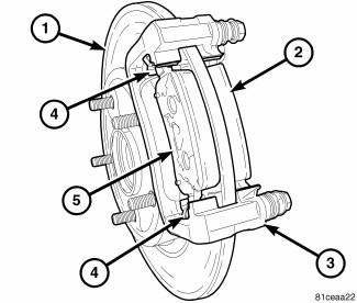
Fig. 5: REAR BRAKE PADS
5. Remove the outboard pad (5) from the adapter bracket.
6. Return the caliper back down over the adapter bracket into mounted position and install the lower guide pin bolt finger tight.
7. Slowly pump the brake pedal until the caliper fingers touch the outboard surface of the brake rotor.
Release the pedal.
8. Remove the brake caliper lower guide pin bolt.
9. Swing the caliper assembly upward, pivoting off the upper guide pin, until clear of the adapter bracket.
10. Reinstall the outboard pad in the adapter bracket.
11. Open the caliper bleeder screw at least one full turn.
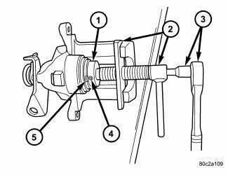
Fig. 6: SEATING PISTON WITH SPECIAL TOOL
12. Seat (bottom) the caliper piston in the bore as follows:
- Assemble a 3/8 in. drive ratchet handle and an extension (3).
- Insert the extension through Special Tool 8807-1 (2).
- Place Special Tool 8807-2 (1) on the end of the extension.
- Insert lugs on Special Tool 8807-2 into notches in face of caliper piston (5).
- Thread the screw drive on 8807-1 down until it contacts the top of 8807-2 which is against the caliper piston. Do not over tighten the screw-drive. Damage to the piston can occur.
- Turn 8807-2 with the ratchet, rotating the piston in a clockwise direction until fully seated (bottomed) in the bore. It may be necessary to turn 8807-1 with 8807-2 to start the process of piston retraction.
13. Close the bleeder screw.
14. Return the caliper back down over the adapter bracket into mounted position and install the lower guide pin bolt finger tight.
15. Have a helper pump the brake pedal three or four times and hold it in the down position.
16. With the pedal in the down position, open the bleeder screw at least one full turn and let out fluid and air, if any.
17. Once the brake pedal has dropped, close the bleeder screw. Once the bleeder screw is closed, release the brake pedal.
18. Repeat the previous three steps until all trapped air is removed.
19. Tighten the guide pin bolt to 35 N.m (26 ft. lbs.).
20. Repeat the above procedure on the opposite rear brake caliper as necessary.
21. Check brake pedal travel and feel. If pedal travel is still excessive or if the pedal feels excessively spongy, repeat the entire procedure as necessary.
22. Install the tire and wheel assembly. Install and tighten wheel mounting nuts to 135 N.m (100 ft. lbs.).
23. Lower the vehicle.
24. Test drive the vehicle to verify the brakes are operating properly and pedal feel is correct.
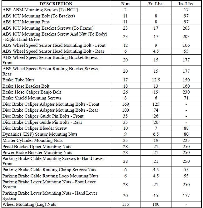
SPECIFICATIONS
BRAKE FASTENER TORQUE
SPECIAL TOOLS
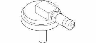
Fig. 7: Adapter, Master Cylinder Pressure Bleed Cap 6921
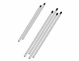
Fig. 8: Bleeder Tubes 8358A
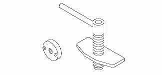
Fig. 9: Retractor, Rear Caliper Piston 8807
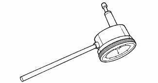
Fig. 10: Dial Indicator 9524
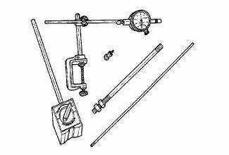
Fig. 11: Dial Indicator C-3339A
 Diagnosis and Testing
BASE BRAKE SYSTEM
NOTE: There are three diagnosis charts following that cover the RED
BRAKE
WARNING INDICATOR LAMP, BRAKE NOISE and OTHER BRAKE CONDITIONS.
RED BRAKE WARNING INDICATOR LAMP ...
 Electrical
SWITCH, BRAKE FLUID LEVEL
Description
The brake fluid level switch (2) is mounted through the center of the fluid
reservoir. The switch can be serviced
separately from the master cylinder fluid r ...
See also:
Diagnosis and Testing
ELECTRIC BACKLIGHT (EBL) SYSTEM
NOTE: Illumination of the defogger switch indicator lamp does not
necessarily mean
that electrical current is reaching the rear window glass and/or the outside ...
Relay, trailer tow
DESCRIPTION
Fig. 40: Identifying Relay & Terminals
Vehicles equipped with an optional trailer tow preparation package have four
trailer tow relays, one each for the
trailer tow stop/turn ri ...
Tube, exhaust gas recirculation (EGR)
Removal
2.7L - LOWER TUBE
Fig. 50: Lower Exhaust Gas Recirculation Tube - 2.7L
WARNING: The normal operating temperature of the exhaust gas
recirculate (EGR)
valve and tube is very ...
