Dodge Journey: Relay, trailer tow
DESCRIPTION
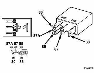
Fig. 40: Identifying Relay & Terminals
Vehicles equipped with an optional trailer tow preparation package have four trailer tow relays, one each for the trailer tow stop/turn right and left and one each for the trailer stop lamp right and left. The trailer tow relays are conventional International Standards Organization (ISO) micro relays. Relays conforming to the ISO specifications have common physical dimensions, current capacities, terminal patterns, and terminal functions.
Each relay is contained within a small, rectangular, molded plastic housing and is connected to all of the required inputs and outputs through five integral male spade-type terminals that extend from the relay base plate.
The trailer tow relays are included with the trailer tow preparation wire harness that is shipped loose in the glove box for customer or dealer installation at the rear of the vehicle. A trailer tow stop/turn relay is located behind the rear fascia below each outer tail lamp, while a trailer stop lamp relay is located behind the rear fascia below each outboard end of the rear bumper reinforcement. Each relay and connector is wrapped within an isolator envelope for sound deadening and anti-rattle protection.
Any of the trailer tow relays cannot be adjusted or repaired and, if ineffective or damaged, the affected unit must be replaced.
OPERATION
The trailer tow relays are electromechanical switches that use a low current input from the Totally Integrated Power Module (TIPM) to the tail lamps to control a high current output to the trailer brake and turn signal lamps. Within each relay are an electromagnetic coil, a movable contact and two fixed contact points. A resistor is connected in parallel with the coil, and helps to dissipate voltage spikes and electromagnetic interference that can be generated as the field of the relay coil collapses.
The movable common supply contact point is held against the fixed normally closed contact point by spring pressure. When the relay coil is energized, an electromagnetic field is produced by the coil windings. This field draws the movable contact away from the normally closed contact, and holds it against the normally open contact. When the relay coil is de-energized, spring pressure returns the movable contact back against the normally closed contact.
The inputs and outputs of the trailer tow relays include:
- Common Supply Terminal (30) - The common feed terminal of both the left and right trailer tow stop/turn relays is connected to their respective left or right trailer tow stop/turn signal pins of the 4-way trailer tow connector at all times. The common feed terminals of both the left and right trailer tow stop relays is connected to the normally closed (87A) terminal of their respective left or right trailer tow stop/turn relay at all times.
- Coil Ground Terminal (85) - The coil ground terminal of both the left and right trailer tow stop/turn relays is connected to their respective left or right rear turn signal control circuits from the TIPM at all times. The coil ground terminals of both the left and right trailer tow stop relays are connected to the stop lamp control circuit from the TIPM at all times.
- Coil Battery Terminal (86) - The coil battery terminal of both the left and right trailer tow stop/turn relays is connected to a path to ground at all times. The coil battery terminal of both the left and right trailer tow stop relays is connected to their respective left or right rear turn signal control circuits from the TIPM at all times.
- Normally Open Terminal (87) - The normally open terminal of both the left and right trailer tow stop/turn relays is connected to the stop lamp control circuit from the TIPM whenever that relay is energized. The normally open terminal of both the left and right trailer tow stop relays is connected to a path to ground whenever that relay is energized.
- Normally Closed Terminal (87A) - The normally closed terminal of both the left and right trailer tow stop/turn relays is connected are connected to the common supply (30) terminal of their respective left or right trailer tow stop relay whenever the relay is de-energized. The normally closed terminal of both the left and right trailer tow stop relays is not connected to any circuit in this application.
The trailer tow relays and the hard wired circuits for the relays may be diagnosed using conventional diagnostic tools and procedures. However, conventional diagnostic methods will not prove conclusive in the diagnosis of the electronic controls and communication between other modules and devices that provide some features of the trailer tow turn and stop lamp lighting system. The most reliable, efficient, and accurate means to diagnose the electronic controls and communication related to trailer tow turn and stop lamp lighting operation requires the use of a diagnostic scan tool. Refer to the appropriate diagnostic information.
REMOVAL

Fig. 41: Isolator Envelope
TRAILER TOW STOP/TURN RELAYS
1. Disconnect and isolate the battery negative cable.
2. Remove the rear fascia from the vehicle.
3. Disengage the left or right trailer tow stop/turn relay and connector from the isolator envelope (3) secured to the trailer tow wire harness (6) along the left or right body side aperture (2) just below the outer tail lamp.
4. Pull the relay straight out from the wire harness connector.
TRAILER TOW STOP LAMP RELAYS
1. Disconnect and isolate the battery negative cable.
2. Remove the rear fascia from the vehicle. 3. Disengage the left or right trailer tow stop lamp relay and connector from the isolator envelope (4) secured to the trailer tow wire harness (6) on the underside of the rear bumper reinforcement (1) on the left or right side of the 4-way trailer tow connector (5).
4. Pull the relay straight out from the wire harness connector.
INSTALLATION
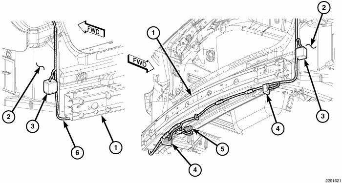
Fig. 42: Isolator Envelope
TRAILER TOW STOP/TURN RELAYS
1. Align the terminals of the left or right trailer tow stop/turn relay with the terminal receptacles of the trailer tow wire harness connector.
2. Firmly and evenly push the relay into the connector until it is fully seated.
3. Insert the relay and connector into the isolator envelope (3) secured to the wire harness (6) along the left or right body side aperture (2) just below the outer tail lamp.
4. Reinstall the rear fascia onto the vehicle.
5. Reconnect the battery negative cable.
TRAILER TOW STOP LAMP RELAYS
1. Align the terminals of the left or right trailer tow stop lamp relay with the terminal receptacles of the trailer tow wire harness connector.
2. Firmly and evenly push the relay into the connector until it is fully seated.
3. Insert the relay and connector into the isolator envelope (4) secured to the trailer tow wire harness (6) on the underside of the rear bumper reinforcement (1) on the left or right side of the 4-way trailer tow connector (5).
4. Reinstall the rear fascia onto the vehicle.
5. Reconnect the battery negative cable.
 Motor, headlamp leveling, export
DESCRIPTION
Fig. 37: Headlamp Leveling Motor
The headlamp leveling motor (1) is located on the rear surface of each front
lamp unit on vehicles equipped
with the headlamp leveling system, which ...
 Switch, backup lamp
DESCRIPTION
Fig. 43: Backup Lamp Switch
Vehicles equipped with a manual transmission (2) have a normally open,
spring-loaded plunger type backup
lamp switch (1). Vehicles with an optional elect ...
See also:
Removal
1. Release the parking brake.
2. Manually release the parking brake cable tension.
3. Raise and support the vehicle.
Fig. 206: TIRE AND WHEEL MOUNTING
4. Remove wheel mounting nuts (3), t ...
DRIVING ON SLIPPERY SURFACES
Acceleration
Rapid acceleration on snow covered, wet, or other slippery
surfaces may cause the front wheels to pull erratically
to the right or left. This phenomenon occurs when
there is a differe ...
Without intermediate shaft
NOTE: The inner tripod joints are designed with a retention feature
that prevents the
tripod rollers from coming out of the inner joint housing up to a specific
load. If
this feature is o ...
