Dodge Journey: Pad, heater
DESCRIPTION
Vehicles equipped with the optional heated seat system have two carbon fiber heated seat elements located in each front seat. One heating element is used for each seat cushion and another for each seat back.
Each of the heated seat elements consist of multiple heating circuits operating in parallel throughout the carbon fiber element. The heated seat elements are captured between the leather trim cover and the seat cushion assembly. If a malfunction occurs in one or more of the individual carbon fiber circuits, the others will continue to provide heat.
The heated seat elements cannot be repaired. If found to be damaged or inoperative, a new heating element assembly must be installed.
OPERATION
One end of the heated seat element is connected to ground at all times through a splice under the seat. Battery current is directed to the other end of the heated seat element by the heated seat module. The heated seat module will energize the heated seat element when the heated seat switch is depressed in the LOW or HIGH position.
As electrical current passes through the heated seat element, the resistance of the wire used in the element disperses some of the electrical current in the form of heat. The heat produced by the heated seat element then radiates through the underside of the seat cushion and seat back trim covers, warming the seat cover and its occupant.
DIAGNOSIS AND TESTING
HEATED SEAT ELEMENT
Refer to the appropriate wiring information for complete circuit schematic or connector pin-out information.
The wire harness connectors for the heating elements are located under the seat.
NOTE: When checking heated seat elements for continuity, be certain to move the heating element being checked. Moving the element, such as sitting in the seat will eliminate the possibility of an intermittent open in the element which would only be evident if the element was in a certain position. Failure to check the element in various positions could result in an incomplete test.
1. Locate and disconnect the seat element electrical connector.
2. Check the resistance between the circuit leading in and out of the suspect heated seat element. The resistance should be between 3.0 - 5.5 ohms for a seat cushion element and 4.0 - 6.0 ohms for a seat back element. If OK, see Diagnosis and Testing . If not OK, replace the inoperative heated seat element.
REMOVAL
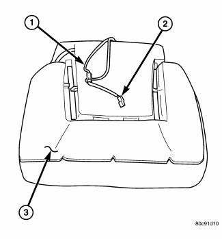
Fig. 7: Removing/Installing Heated Seat Element
NOTE: The factory installed heating element can be removed from foam cushion by carefully peeling the element off along the adhesive lines.
NOTE: Heated seat cushion shown in illustration. Heated seat back similar.
1. Disconnect and isolate the battery negative cable.
2. Remove the appropriate seat cushion trim cover or seat back trim cover.
3. Disconnect the inoperative heated seat cushion or seat back element electrical connectors (2).
4. Peel the heater element off the foam pad, being careful not to remove excessive foam in the process.
INSTALLATION
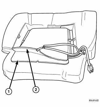
Fig. 8: Identifying Replacement Heating Element And Factory Installed Heating
Element
CAUTION: During the installation of the replacement heating element, be careful not to fold or crease the element assembly. Folds or creases will cause premature failure.
NOTE: Heated seat cushion shown in illustration. Heated seat back similar.
1. Peel off the adhesive backing on the back of the replacement heating element (2) and stick on foam pad directly where the original element was placed (there will be adhesive marks on the foam outlining factory installed element) (1).
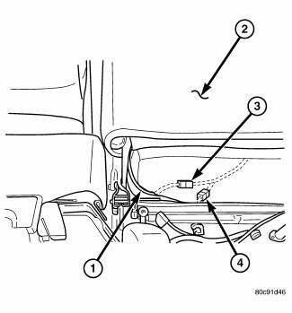
Fig. 9: Connecting New Heating Element Electrical Connectors
2. Connect the new heating element electrical connectors (3 AND 4).
3. Connect the battery negative cable.
4. Verify heated seat system operation.
5. Install the appropriate seat cushion trim cover or seat back trim cover.
NOTE: Make certain the seat wire harness is correctly routed through the seat and seat back. The excess wire between the cushion and back elements should be securely tucked between the rear of the cushion foam and the rear carpet flap of the trim cover. The factory installed heater element should be completely removed from the system and discarded.
 Module, heated seat
DESCRIPTION
Fig. 4: Locating Heated Seat Module
The heated seat module (2) is located under the driver front seat. It has a
single electrical connector (1) and a
push pin style retainer that se ...
 Switch, heated seat
DESCRIPTION
Fig. 10: Locating Accessory Switch Bank Module
Two heated seat switches are located in the center stack of the instrument
panel. The switches are located on the
outer edges of the A ...
See also:
Lines, A/C underbody, extension
Description
Fig. 310: Underbody A/C Extension Lines Description
Models equipped with the rear heating-A/C system use metal lines attached to
the vehicle underbody to carry
refrigerant and engin ...
Pan, oil
Removal
Fig. 259: Identifying Oil Dipstick Tube & Bolt
1. Disconnect and isolate the negative battery cable.
2. Remove the bolt (1) and the engine oil dipstick tube (2).
Fig. 260: Belly ...
Switch, horn
REMOVAL
WARNING: On vehicles equipped with an airbag, refer to Restraint
SERVICE
INFORMATION article for warnings and cautions before servicing the horn
switch.
Fig. 3: Remov ...
