Dodge Journey: Reinforcement, bumper, rear
REMOVAL
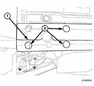
Fig. 25: Rear Bumper Reinforcement
1. Remove rear fascia. See Removal .
2. Support bumper reinforcement (1) on a suitable lifting device.
3. Mark position of bolts (2) on frame rail to aid in installation.
4. Remove bolts (2) attaching rear bumper reinforcement (1) to frame rail.
5. Remove bumper reinforcement (1) from vehicle.
INSTALLATION

Fig. 26: Rear Bumper Reinforcement
1. Position rear bumper reinforcement (1) on vehicle.
2. Install bolts (2) attaching bumper reinforcement to frame rail. Use marks made previously to properly position bumper reinforcement.
3. Tighten bolts (2) to 28 N.m (250 in. lbs.).
4. Install rear fascia.
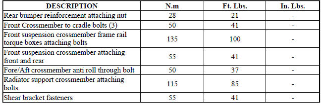
SPECIFICATIONS
FASTENER TORQUE
 Reinforcement, bumper, front
REMOVAL
Fig. 23: Front Bumper Reinforcement
1. Remove the front fascia. See Removal .
2. Support bumper reinforcement (3) on a suitable lifting device.
3. Mark the position of the bolts (1) ...
 Frame
Frame
SPECIFICATIONS
FRAME DIMENSIONS
Frame dimensions are listed in metric scale. All dimensions are from center
to center of Principal Locating
Point (PLP), or from center to center of PLP and fasten ...
See also:
TRAILER TOWING
In this section, you will find safety tips and information
on limits to the type of towing you can reasonably do
with your vehicle. Before towing a trailer, carefully
review this information to tow ...
Diagnosis and Testing
BRAKE LAMP SWITCH
WARNING: To avoid serious or fatal injury on vehicles equipped
with airbags, disable
the Supplemental Restraint System (SRS) before attempting any steering
wheel, s ...
A WORD ABOUT YOUR KEYS
Your vehicle uses a keyless ignition system. This system
consists of a Key Fob with Remote Keyless Entry (RKE)
transmitter and a Wireless Ignition Node (WIN) with
integral ignition switch. You can ...
