Dodge Journey: Fascia, front
REMOVAL

Fig. 1: Pushpins
1. Release hood latch and open hood.
2. Remove the pushpins for the fascia (2) at the radiator support.
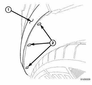
Fig. 2: Pop Rivets
3. Hoist and support vehicle on safety stands.
4. Remove the pop rivets (2) at the wheel well opening.

Fig. 3: Fascia Tabs & Bracket
5. Remove the Torx screw (3) at the wheel well housing.
6. Separate the fascia tabs (2) at the bracket (1).
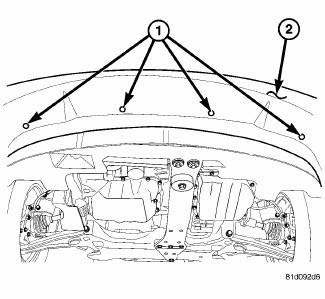
Fig. 4: Lower Pushpins
7. Remove the pushpins (1) for the fascia (2) at the lower closeout panel.

Fig. 5: Fascia & Mounting Tab
8. Slide the fascia (2) out from the mounting tab (1) under the headlamp.
9. Disengage fog lamp wire connector and side marker connector from body harness, if equipped.
10. Disengage the ambient temp sensor wire connector, if equipped.
11. Remove fascia from vehicle.
INSTALLATION
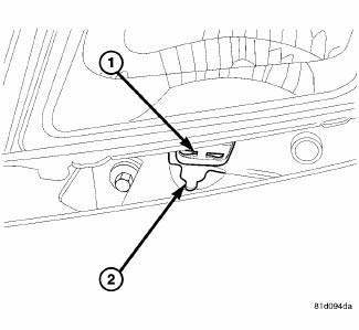
Fig. 6: Fascia & Mounting Tab
1. Install the fascia to the vehicle.
2. Reconnect the ambient temp sensor wire connector, if equipped.
3. Reconnect the fog lamp wire connector and side marker connector from body harness, if equipped.
4. Slide the fascia (2) into the mounting tab (1) under the headlamp.

Fig. 7: Lower Pushpins
5. Install the pushpins (1) for the fascia (2) at the lower closeout panel.
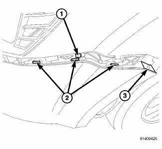
Fig. 8: Fascia Tabs & Bracket
6. Insert and snap into place the fascia tabs (2) at the bracket (1).
7. Install the Torx screw (3) at the wheel well housing.

Fig. 9: Pop Rivets
8. Install the pop rivets (2) at the wheel well opening.
9. Lower the vehicle.
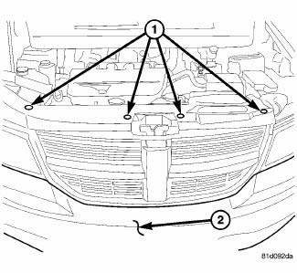
Fig. 10: Pushpins
10. Install the pushpins for the fascia (2) at the radiator support.
11. close the hood and check for proper fit.
 Bumpers
...
 Fascia, front lower, closeout
REMOVAL
Fig. 11: Lower Fascia
1. Remove fasteners (5) to lower closeout.
Fig. 12: Push Pins - Front Lower Fascia
2. Remove push pins (1) to lower closeout.
3. Remove the front lower fascia.
...
See also:
Cover(s), engine timing
Removal
Fig. 349: FRONT SPLASH SHIELDS
1. Disconnect and isolate negative battery cable.
2. Drain cooling system.
3. Remove coolant pressure container.
4. Remove right front wheel and bel ...
Disassembly
NOTE: The rear heater-A/C housing must be removed from the vehicle for
service of
the mode door actuator and blend door actuator and it must be disassembled
for service of the A/C evaporator ...
Control, A/C and heater, rear
DESCRIPTION
The A/C-heater controls allows the driver and front seat passenger and the
intermediate seat passengers the
ability to regulate air temperature as well as fan speed for the rear
heat ...
