Dodge Journey: Removal, Installation
REMOVAL

Fig. 48: Lower Instrument Panel Knee Blocker
1. Disconnect and isolate the battery negative cable.
2. Remove the lower instrument panel knee blocker.
3. Remove upper steering column shroud.
4. Remove the instrument cluster bezel, reposition the instrument, and remove the upper WIN bracket attaching screw (1).
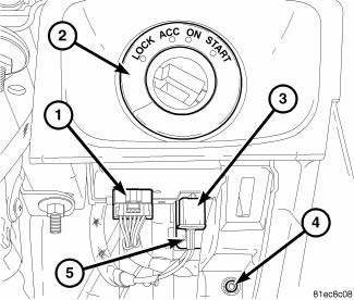
Fig. 49: WIN Electrical Connector And Antenna Connector
5. Disconnect the WIN electrical connector (1) and the antenna connector (3) from the WIN.
6. Utilize a trim stick or equivalent and gently pry WIN trim ring (2) away from the instrument panel.
7. Remove the lower WIN attaching screw (5).
8. Remove the lower WIN bracket attaching screw (4).
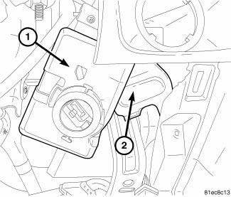
Fig. 50: Bracket-Wireless Ignition Node
9. Rotate the WIN (1) and (2) bracket to assist in removal from the instrument panel.
10. Remove the WIN from the instrument panel opening.
INSTALLATION
NOTE: The WIN initialization procedure is required whenever the WIN or shaft lock module is replaced on vehicles equipped with the shaft lock module.

Fig. 51: Bracket-Wireless Ignition Node
1. Rotate and position the WIN (1) and bracket (2) into the to instrument panel opening.

Fig. 52: WIN Electrical Connector And Antenna Connector
2. Install the lower WIN bracket attaching screw (4).
3. Install the lower WIN attaching screw (5).
4. Connect the WIN electrical connector (1) and antenna connector (3) to the WIN.
5. Install the WIN trim ring (2).
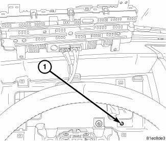
Fig. 53: Lower Instrument Panel Knee Blocker
6. Install the upper WIN bracket attaching screw (1) and reposition the instrument cluster into the instrument panel and install the instrument cluster bezel.
7. Install upper steering column shroud.
8. Install knee blocker.
9. Connect negative battery cable.
10. If necessary, program the WIN.
 Description, Operation
DESCRIPTION
This vehicle is equipped with a Wireless Ignition Node (WIN) (1). The WIN and
the FOB with Integrated Key
(FOBIK) are the primary components of the keyless ignition system. The only
...

See also:
Sensor, variable line pressure
DESCRIPTION
Fig. 390: Identifying Variable Line Pressure Sensor
- PRESSURE CONTROL SOLENOID
- LINE PRESSURE SENSOR
- SHOULDER SCREW
- VARIABLE LINE PRESSURE HEADER
- MANUAL SHAFT
- SC ...
Description, Operation
DESCRIPTION
Fig. 418: Identifying Ignition Key/Switch Positions
- LOCK
- ACC
- ON
- START
The Brake Transmission Shifter/Ignition Interlock (BTSI) is a solenoid
operated system that ...
VEHICLE IDENTIFICATION NUMBER
The Vehicle Identification Number (VIN) is on the left
front corner of the instrument panel and is visible from
outside of the vehicle through the windshield. This
number also appears on the Automo ...
