Dodge Journey: Module, steering column
DESCRIPTION
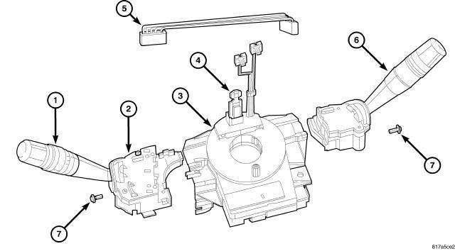
Fig. 47: Steering Control Module
This vehicle is equipped with a Steering Control Module (SCM) that is internal to the left multi-function switch housing (2). The left (lighting) multi-function switch is located on the left side of the steering column, just below the steering wheel. This switch is the primary control for the interior and exterior lighting systems. The only visible components of the switch are the control stalk (1), control knob and control sleeve that extend through the steering column shrouds on the left side of the column. The remainder of the switch including its mounting provisions and electrical connections are concealed beneath the shrouds.
The switch housing and controls are constructed of molded black plastic. A single screw (7) through a mounting tab integral to the back of the switch housing, and a slide tab integral to the bottom of the switch housing secure the switch to the mounting bracket integral to the clockspring (3). A connector receptacle containing seven terminal pins is integral to the inboard end of the switch housing and connects the SCM through a jumper wire harness (5) directly to the right (wiper) multi-function switch (6). A second connector receptacle containing four terminal pins is integral to the back of the switch housing and connects the SCM to the vehicle electrical system through a dedicated takeout and connector of the instrument panel wire harness.
The SCM cannot be adjusted or repaired. If ineffective or damaged the entire left multi-function switch must be replaced. Refer to Electrical - Lamps and Lighting/Lamps/Lighting - Exterior/SWITCH, Multifunction - Removal . The clockspring (with the multi-function switch mounting bracket), the left multi-function switch (with the SCM), the right multi-function switch and the jumper wire harness are each available for separate service replacement.
OPERATION
The Steering Control Module (SCM) communicates over the Local Interconnect Network (LIN) data bus with other electronic modules in the vehicle and/or a diagnostic scan tool. The horn switch circuits pass through the clockspring to the Cab Compartment Node (CCN) and the CCN sends a CAN message to the Totally Integrated Power Module (TIPM) to control the horn. The CCN stores Diagnostic Trouble Codes (DTC's) for the SCM.
The right (wiper) multi-function switch has several inputs to the CCN.
The SCM is connected to a fused B(+) circuit and receives a path to ground at all times. These connections allow it to remain functional regardless of the ignition switch position. The driver airbag squib circuits of the clockspring, the horn, and the speed control switch circuits pass through the SCM, but the SCM does not monitor, and has no control outputs related to these circuits. Any other input to the SCM that would cause a vehicle system to function but does not require that the ignition switch be in the On position, such as turning on the lights or sounding the horn, prompts the SCM to wake up and transmit on the CAN data bus.
The most reliable, efficient, and accurate means to diagnose the SCM, the CAN data bus, the hard wired inputs or the electronic communication related to SCM operation requires the use of a diagnostic scan tool. Refer to the appropriate diagnostic service information.
The integral SCM is not available for separate service replacement. If found inoperative or defective, the entire left (lighting) multi-function switch must be replaced.
DIAGNOSIS AND TESTING
STEERING CONTROL MODULE
WARNING: To avoid serious or fatal injury on vehicles equipped with airbags, disable the Supplemental Restraint System (SRS) before attempting any steering wheel, steering column, airbag, seat belt tensioner, impact sensor, or instrument panel component diagnosis or service. Disconnect and isolate the battery negative (ground) cable, then wait two minutes for the system capacitor to discharge before performing further diagnosis or service.
This is the only sure way to disable the SRS. Failure to take the proper precautions could result in accidental airbag deployment.
The hard wired circuits between components related to the Steering Control Module (SCM) may be diagnosed using conventional diagnostic tools and procedures. Refer to SYSTEM WIRING DIAGRAMS . The wiring information includes wiring diagrams, proper wire and connector repair procedures, details of wire harness routing and retention, connector pin-out information and location views for the various wire harness connectors, splices and grounds.
However, conventional diagnostic methods will not prove conclusive in the diagnosis of the SCM or the electronic controls or communication between modules and other devices that provide some features of the SCM. The most reliable, efficient, and accurate means to diagnose the SCM or the electronic controls and communication related to SCM operation requires the use of a diagnostic scan tool. Refer to the appropriate diagnostic service information.
 Removal, Installation
REMOVAL
REMOVAL - NGC CONTROLLER
Fig. 39: Remove/Install PCM
NOTE: USE THE SCAN TOOL TO REPROGRAM THE NEW POWERTRAIN CONTROL
MODULE (PCM) WITH THE VEHICLES ORIGINAL IDENTIFICATION NUMBER
( ...

See also:
Description, Operation
DESCRIPTION
The generator is belt-driven by the engine. It is serviced only as a complete
assembly. If the generator fails for
any reason, the entire assembly must be replaced. The generator produ ...
REPLACEMENT PARTS
Use of genuine MOPAR parts for normal/scheduled
maintenance and repairs is highly recommended to ensure
the designed performance. Damage or failures
caused by the use of non-MOPAR parts for mainten ...
Removal, Installation
REMOVAL
WARNING: Disable the airbag system before attempting any steering
wheel, steering
column or instrument panel component diagnosis or service. Disconnect
and isolate the negati ...
