Dodge Journey: Description, Operation
DESCRIPTION
POWERTRAIN CONTROL MODULE (PCM)
The Powertrain Control Module (PCM) is a digital computer containing a microprocessor. The PCM receives input signals from various switches and sensors referred to as Powertrain Control Module Inputs. Based on these inputs, the PCM adjusts various engine and vehicle operations through devices referred to as Powertrain Control Module Outputs.
NOTE: PCM Inputs:
- Air Conditioning Pressure Transducer
- ASD/Main Relay
- Battery Voltage
- Brake Switch
- Camshaft Position Sensor
- Crankshaft Position Sensor
- Distance Sensor (from transmission control module)
- EGR Position Feedback (if equipped)
- Engine Coolant Temperature Sensor
- Heated Oxygen Sensors
- Ignition sense
- Inlet Air Temperature Sensor
- Knock Sensor
- Manifold Absolute Pressure (MAP) Sensor
- Park/Neutral (from trans range sensor)
- Power Steering Pressure Switch
- Proportional Purge Sense
- CAN C Bus
- Speed Control
- Transmission Control Relay (Switched B+)
- Transmission Pressure Switches
- Transmission Temperature Sensor
- Transmission Input Shaft Speed Sensor
- Transmission Output Shaft Speed Sensor
- Vehicle Speed
NOTE: PCM Outputs:
- Air Conditioning Clutch Relay
- Data Link Connector (CAN C Bus)
- Double Start Override
- EGR Solenoid (if equipped)
- Fuel Injectors
- Generator Field
- High Speed Fan Relay
- Ignition Coils
- Natural Vacuum Leak Detection
- Low Speed Fan Relay
- MTV Actuator
- Proportional Purge Solenoid
- SRV Valve
- Speed Control Relay
- Speed Control Vent Relay
- Speed Control Vacuum Relay
- Torque Reduction Request
- Transmission Control Relay
- Transmission Solenoids
- 5 Volt Output
Based on inputs it receives, the powertrain control module (PCM) adjusts fuel injector pulse width, idle speed, ignition timing, and canister purge operation and EGR if equipped. The PCM regulates the cooling fans, air conditioning and speed control systems. The PCM changes generator charge rate by adjusting the generator field.
The PCM adjusts injector pulse width (air-fuel ratio) based on the following inputs.
- Manifold Absolute Pressure
- Engine Speed (crankshaft position sensor)
- Battery Voltage
- Inlet Air Temperature Sensor
- Engine Coolant Temperature
- Exhaust Gas Oxygen Content (heated oxygen sensors)
- Throttle Position
The PCM adjusts engine idle speed through the idle air control motor based on the following inputs.
- Brake Switch
- Engine Coolant Temperature
- Engine Speed (crankshaft position sensor)
- Park/Neutral
- Transaxle Gear Engagement
- Throttle Position
- Vehicle Speed (from Transmission Control Module)
The PCM adjusts ignition timing based on the following inputs.
- Inlet Air Temperature
- Engine Coolant Temperature
- Engine Speed (crankshaft position sensor)
- Knock Sensor
- Manifold Absolute Pressure
- Park/Neutral (from trans range sensor)
- Transaxle Gear Engagement
- Throttle Position
The camshaft and crankshaft signals are sent to the Powertrain Control Module (PCM). If the PCM does not receive both signals within approximately one second of engine cranking, it deactivates the fuel pump. When deactivated, power is shut off to the fuel injectors, ignition coils, fuel pump and the heating element in each oxygen sensor.
The PCM contains a voltage converter that changes battery voltage to a regulated 5.0 volts. The 5.0 volts power the camshaft position sensor, and crankshaft position sensor. The PCM also provides a regulated 5.0 volts supply for the, manifold absolute pressure sensor, throttle position sensor and EGR (if equipped).
The PCM engine control strategy prevents reduced idle speeds until after the engine operates for 320 km (200 miles). If the PCM is replaced after 320 km (200 miles) of usage, update the mileage in new PCM. Use the scan tool to change the mileage in the PCM. Refer to the appropriate Powertrain Diagnostic Service Information and the scan tool. If equipped with SKREEM, must use SKREEM function to program VIN number in new PCM.
TRANSMISSION CONTROL
CVI CALCULATION
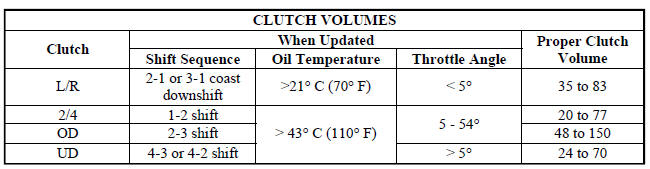
An important function of the PCM is to monitor Clutch Volume Index (CVI). CVIs represent the volume of fluid needed to compress a clutch pack.
The PCM monitors gear ratio changes by monitoring the Input and Output Speed Sensors. The Input, or Turbine Speed Sensor sends an electrical signal to the PCM that represents input shaft rpm. The Output Speed Sensor provides the PCM with output shaft speed information.
By comparing the two inputs, the PCM can determine transaxle gear ratio. This is important to the CVI calculation because the PCM determines CVIs by monitoring how long it takes for a gear change to occur .
Fig. 38: Example of CVI Calculation
- - OUTPUT SPEED SENSOR
- - OUTPUT SHAFT
- - CLUTCH PACK
- - SEPARATOR PLATE
- - FRICTION DISCS
- - INPUT SHAFT
- - INPUT SPEED SENSOR
- - PISTON AND SEAL
Gear ratios can be determined by using the scan tool and reading the Input/Output Speed Sensor values in the "Monitors" display. Gear ratio can be obtained by dividing the Input Speed Sensor value by the Output Speed Sensor value.
For example, if the input shaft is rotating at 1000 rpm and the output shaft is rotating at 500 rpm, then the PCM can determine that the gear ratio is 2:1. In direct drive (3rd gear), the gear ratio changes to 1:1. The gear ratio changes as clutches are applied and released. By monitoring the length of time it takes for the gear ratio to change following a shift request, the PCM can determine the volume of fluid used to apply or release a friction element.
The volume of transmission fluid needed to apply the friction elements are continuously updated for adaptive controls. As friction material wears, the volume of fluid need to apply the element increases.
Certain mechanical problems within the clutch assemblies (broken return springs, out of position snap rings, excessive clutch pack clearance, improper assembly, etc.) can cause inadequate or out-of-range clutch volumes.
Also, defective Input/Output Speed Sensors and wiring can cause these conditions. The following chart identifies the appropriate clutch volumes and when they are monitored/updated:
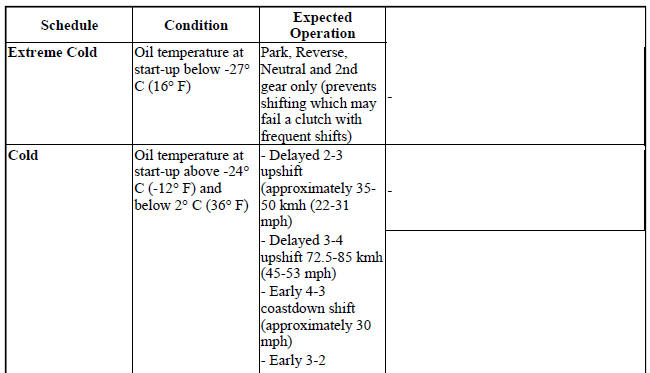
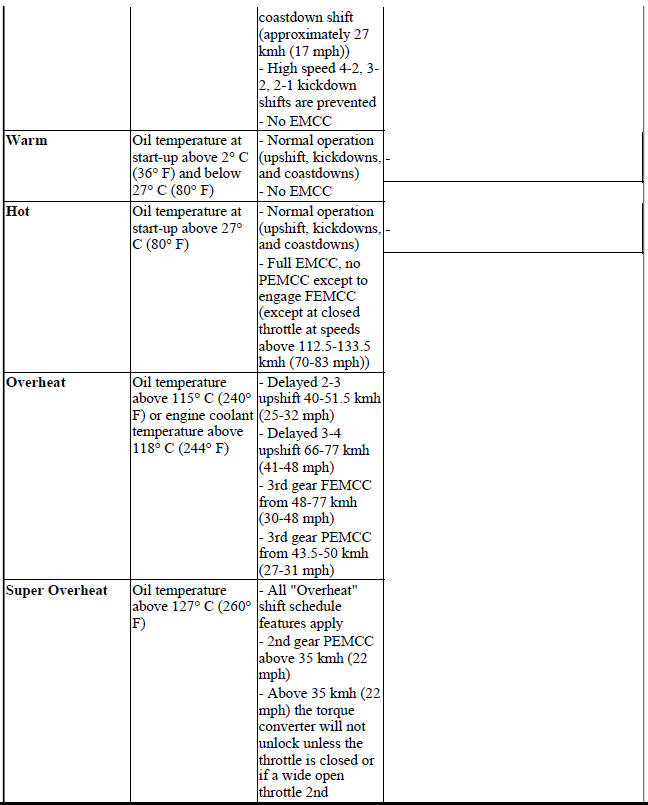
SHIFT SCHEDULES
The PCM has programming that allows it to select a variety of shift schedules. Shift schedule selection is dependent on the following:
- Shift lever position
- Throttle position
- Engine load
- Fluid temperature
- Software level
As driving conditions change, the PCM appropriately adjusts the shift schedule. Refer to the following chart to determine the appropriate operation expected, depending on driving conditions.

SENSOR RETURN - PCM INPUT
The sensor return circuit provides a low electrical noise ground reference for all of the systems sensors. The sensor return circuit connects to internal ground circuits within the Powertrain Control Module (PCM).
PCM REPLACEMENT
DESCRIPTION
Use the scan tool to reprogram the new pcm with the vehicle's original identification number (vin) and the vehicle's original mileage. If this step is not done a Diagnostic Trouble Code (DTC) may be set.
PCM GROUND
Ground is provided through multiple pins of the PCM connector. Depending on the vehicle there may be as many as two different ground pins. There are power grounds and sensor grounds.
The power grounds are used to control the ground side of relays, solenoids, ignition coil or injectors. The signal ground is used for any input that uses sensor return for ground, and the ground side of any internal processing component.
The PCM case is shielded to prevent RFI and EMI. The PCM case is grounded and must be firmly attached to a good, clean body ground.
Internally all grounds are connected together, however there is noise suppression on the sensor ground. For EMI and RFI protection the housing and cover are also grounded via the mounting screws AND bracket to the chassis, separately from the ground pins.
OPERATION
The PCM supplies two regulated 5 volts supplies - a 5V primary and a 5V secondary (auxiliary) to the following sensors:
- Camshaft Position Sensor (5V secondary)
- Crankshaft Position Sensor (5V primary)
- EGR Position feedback sensor (5V secondary) (if equipped)
- Engine coolant temperature sensor (connected to 5V internal via a pullup resistor)
- Inlet Air Temperature Sensor (connected to 5V internal via a pullup resistor)
- Knock sensor (connected to 5V internal via a pullup resistor)
- Manifold absolute pressure sensor (5V secondary)
- Oil Pressure Switch (connected to 5V internal via pullup resistor)
- Pedal Value Sensor #1 (5V Primary)
- Pedal Value Sensor #2 (5V Secondary)
- SRV Position Feedback Sensor (5V Secondary)
- Throttle Position Sensors (5V Primary)
- Variable Line Pressure Sensor (5V Secondary)

 Standard procedure
PCM/ECM REPROGRAMMING - GAS
Follow the instructions in order.
OBTAINING DIAGNOSTIC TROUBLE CODES
BULB CHECK
Key on: Bulb illuminated until vehicle starts, as long as all once per trip
(readiness ...
See also:
ELECTRONIC VEHICLE INFORMATION CENTER (EVIC) — IF EQUIPPED
The Electronic Vehicle Information Center (EVIC) features
a driver-interactive display. It is located in the
instrument cluster below the fuel and temperature
gauges. Vehicles equipped with steerin ...
Operation
SYSTEM
The Powertrain Control Module (PCM) monitors many different circuits in the
fuel injection, ignition, emission
and engine systems. If the PCM senses a problem with a monitored circuit often ...
Lamp, fog, rear export
Removal
BULB
Fig. 11: Rear Fascia Wire Harness Connector
1. Disconnect and isolate the battery negative cable.
2. Remove the rear fog lamp from the rear fascia.
3. Disconnect the rear fa ...
