Dodge Journey: Removal
LEFT-HAND DRIVE
NOTE: The ABM is only separately serviceable for non-HSA (Hill Start Assist) equipped vehicles. Do not remove the ABM for vehicles equipped with HSA.
1. Disconnect the negative (ground) cable from the battery and isolate it.
2. Remove the engine appearance cover.
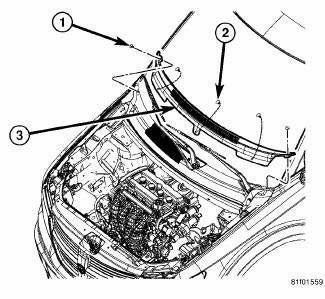
Fig. 3: Cowl Top Screen
3. Remove the two push-pins (1) securing the cowl top screen at the ends. Remove the remaining push-pins (2). Remove the cowl top screen (3).
4. Remove the wiper arms.
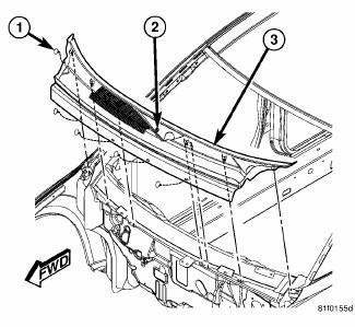
Fig. 4: Cowl Screen
5. Remove the push-pins (1) securing the cowl screen to the wheelhouse brace and cowl. Rotate the screw (2) in the center of the cowl screen 90º clockwise to release the screen. Remove the cowl screen (3).
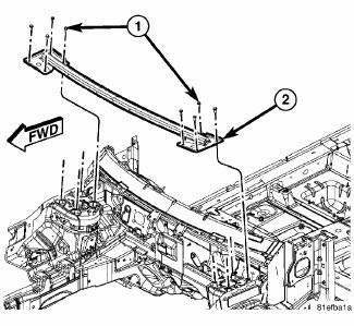
Fig. 5: Wheelhouse Brace
6. Remove the eight mounting bolts (four each side) (1) securing the wheel house brace to the strut towers.
7. Remove the wheelhouse brace (2).
8. Remove two screws, then remove the fresh air plenum.
9. Raise and support the vehicle.
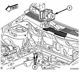
Fig. 6: Locating Integrated Control Unit (ICU)
10. Loosen, but do not remove, the two mounting screws (2) attaching the ICU (1) mounting bracket to the body.
11. Lift the ICU and mounting bracket (1) upward to near the top of the slots in the bracket, then snug one or both of the mounting screws (2) to hold the ICU in this position.
12. Lower the vehicle.
CAUTION: Before disassembling the ICU, the ICU must be thoroughly cleaned.
This must be done to prevent dirt particles and debris from entering into vital areas of the ICU.
13. Thoroughly clean all surfaces of the ICU and brake tubes. Use only a solvent such as Mopar Brake Parts Cleaner or equivalent.

Fig. 7: ABM Connector Release Tabs
NOTE: Use this figure in the following step to release the ABM harness connector cover. It shows the location of the release tabs.

Fig. 8: Wiring Harness Connector At ABM
- - ABM (PART OF ICU)
- - WIRING HARNESS CONNECTOR
14. Disconnect the ABM harness connector from the Antilock Brake Module (ABM). To do so:
- Depress the tabs on each side of the connector cover, then
- Pull outward and upward on the lower half of the cover until it locks into position pointing straight outward (2). The connector can then be pulled straight outward off the ABM (1).
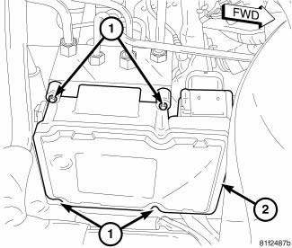
Fig. 9: ABM Mounting
15. Remove the four screws (1) attaching the ABM (2) to the HCU. A Torx T20 bit approximately 2 inches long works well.
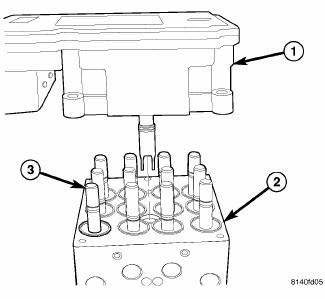
Fig. 10: Identifying ABM, HCU, & Solenoid Valve Stem
- - ABM
- - HCU
- - SOLENOID VALVE STE
CAUTION: When removing the ABM from the HCU, be sure to completely separate the two components (approximately 38 mm (1.5 inches)) before removing the ABM. Otherwise, damage to the pressure sensor or pump motor connection may result, requiring HCU replacement.
Do not to touch the sensor terminals on the HCU side or the contact pads on the ABM side as this may result in contamination and issues in the future.
16. Separate the ABM (1) from the HCU (2).
RIGHT-HAND DRIVE
NOTE: The ABM is only separately serviceable for non-HSA (Hill Start Assist) equipped vehicles. Do not remove the ABM for vehicles equipped with HSA.
1. Disconnect the negative (ground) cable from the battery and isolate it.
2. Remove air inlet hose (1) between air cleaner housing and engine.
CAUTION: Before disassembling the ICU, the ICU must be thoroughly cleaned.
This must be done to prevent dirt particles and debris from entering into vital areas of the ICU.
3. Thoroughly clean all surfaces of the ICU and brake tubes. Use only a solvent such as Mopar Brake Parts Cleaner or equivalent.
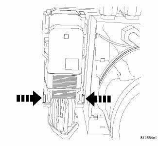
Fig. 11: ABM Connector Release Tabs
NOTE: Use this figure in the following step to release the ABM harness connector cover. It shows the location of the release tabs.
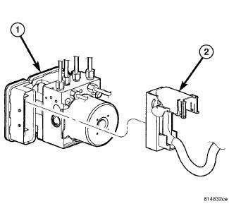
Fig. 12: Wiring Harness Connector At ABM
- - ABM (PART OF ICU)
- - WIRING HARNESS CONNECTOR
4. Disconnect the ABM harness connector from the Antilock Brake Module (ABM). To do so:
- Depress the tabs on each side of the connector cover, then
- Pull outward and upward on the lower half of the cover until it locks into position pointing straight outward (2). The connector can then be pulled straight outward off the ABM (1).
Fig. 13: ABM Mounting Screws
- - MOUNTING SCREWS
- - ABM
5. Remove the four screws (1) attaching the ABM (2) to the HCU.

Fig. 14: ABM Assembly To HCU
- - ABM
- - HCU
- - SOLENOID VALVE STEM
CAUTION: When removing the ABM from the HCU, be sure to completely separate the two components (approximately 38 mm (1.5 inches)) before removing the ABM. Otherwise, damage to the pressure sensor or pump motor connection may result, requiring HCU replacement.
Do not to touch the sensor terminals on the HCU side or the contact pads on the ABM side as this may result in contamination and issues in the future.
6. Separate the ABM (1) from the HCU (2).
 Description, Operation
DESCRIPTION
Fig. 2: Antilock Brake Module
- ANTILOCK BRAKE MODULE (ABM)
- HYDRAULIC CONTROL UNIT (HCU)
- PUMP/MOTOR
The Antilock Brake Module (ABM) is a microprocessor-based device which ...
 Installation
LEFT-HAND DRIVE
1. Clean any debris off the mating surfaces of the HCU and ABM.
CAUTION: When installing new O-rings or solenoid valve stem seals,
do not use
any type of lubricant.
...
See also:
Seal, oil pump
REMOVAL
Fig. 367: Removing Oil Pump Seal
- SEAL PULLER C-3981-B
- OIL PUMP SEAL
1. Remove transaxle from vehicle.
2. Using Seal Puller C-3981B (1) , remove oil pump seal (2).
INSTALLA ...
Duct, defroster
REMOVAL
WARNING: Disable the airbag system before attempting any steering
wheel, steering
column or instrument panel component diagnosis or service. Disconnect
and isolate the negat ...
RECREATIONAL TOWING (BEHIND MOTORHOME, ETC.)
TOWING THIS VEHICLE BEHIND ANOTHER VEHICLE (Flat Towing With All Four
Wheels On The Ground)
Recreational towing for this vehicle is not recommended.
NOTE: If the vehicle requires towing, make sure ...
